Rotary conducting structure

A conductive structure and external insulation technology, applied in the direction of rotating collectors, circuits, collectors, etc., can solve the problem of unstable conductive connection of conductive rings

Inactive Publication Date: 2015-12-09
CHINA AVIATION OPTICAL-ELECTRICAL TECH CO LTD
View PDF8 Cites 9 Cited by
  • Summary
  • Abstract
  • Description
  • Claims
  • Application Information

AI Technical Summary

Problems solved by technology

[0004] The purpose of the present invention is to provide a rotating conductive structure in which impact and collision will not occur between the ball and the conductive outer ring, and the conductive outer ring will not float radially, so as to solve the unstable conductive connection of the existing rotary conductive ring The problem

Method used


Image

  • Rotary conducting structure

Examples


Embodiment Construction

[0014] The rotating conductive structure of the present invention will be described in detail below in conjunction with the accompanying drawings:

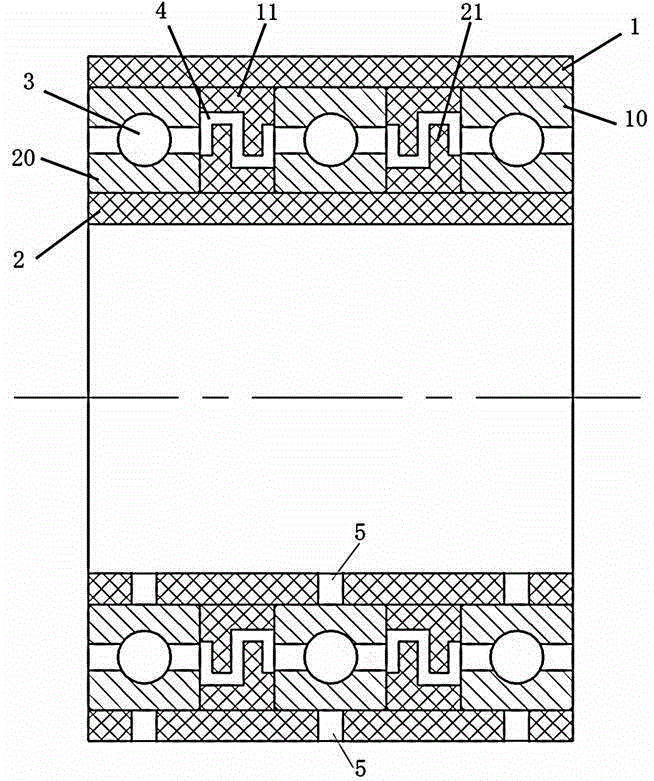
[0015] Embodiment 1 of the rotating conductive structure of the present invention: as figure 1 As shown, it includes the outer insulating sleeve 1 and the inner insulating sleeve 2 arranged coaxially, and three bearings are installed in the annular space enclosed between the inner and outer insulating sleeves, and the three bearings are evenly spaced in the axial direction. The axis coincides with the axis of the inner and outer insulating sleeves, and each bearing has a bearing outer ring 10 fixedly connected to the inner peripheral surface of the outer insulating sleeve 1 and a bearing inner ring 20 fixedly connected to the outer peripheral surface of the inner insulating sleeve 2. Both the inner ring and the outer ring of the bearing are made of conductive materials, and the conductive balls 3 are rolled between the inner rings...


PUM


Abstract

The invention provides a rotary conducting structure. The rotary conducting structure comprises an inner insulation sleeve and an outer insulation sleeve, the axes of the inner and outer insulation sleeves extend in the front and back direction, the inner insulation sleeve is arranged coaxial with the outer insulation sleeve, and at least one bearing is arranged in an annular space formed between the inner and outer insulation sleeves. Each bearing includes a circumferentially enclosed bearing outer ring, a circumferentially enclosed bearing inner ring and a conducting ball, wherein the bearing outer ring is fixedly assembled at the internal circumferential surface of the outer insulation sleeve, the bearing inner ring is fixedly assembled at the external circumferential surface of the inner insulation sleeve, and the conductive ball is connected between the bearing inner ring and the bearing outer ring. The bearing inner and outer rings of the rotary conducting structure are enclosed circumferentially and fixed to the inner insulation sleeve and the outer insulation sleeve which are arranged coaxially, the radial sizes of the different positions of the annular space formed between the bearing inner and outer rings are the same, the ball makes stable and unchanged contact with the bearing inner and outer rings when rotating circumferentially in the annular space in a circulated manner, and the rotary conducting performance is high.

Description

technical field [0001] The invention relates to the field of conductive connection, in particular to a rotating conductive structure. Background technique [0002] At present, in the field of electric slip rings, the brush and the conductive ring mainly adopt the sliding contact method, and composite brush blocks or precious metal monofilaments or fiber brushes are used to make sliding conductive contact with the conductive ring. When the electric slip ring is applied to high-power transmission, the above three Both need to use multi-channel parallel to transmit power together. Due to the influence of machining accuracy and assembly accuracy, the actual power transmitted by each channel is not the same. When the design redundancy is small, due to the difference in actual transmission power, some path brushes will burn out, resulting in product failure; when the design redundancy is large, the axial dimension needs to be increased, and the product cost will increase according...

Claims


Application Information

Patent Timeline
Patent Type & Authority Applications(China)
IPC IPC(8): H01R39/64H01R39/02
Inventor 乔永红朱晓东
Owner CHINA AVIATION OPTICAL-ELECTRICAL TECH CO LTD
Why Eureka
Try Eureka