Supercharge Your Innovation With Domain-Expert AI Agents!

Vacuum cleaner nozzle with sealing edge

A vacuum cleaner, edge technology, applied in the direction of vacuum cleaners, suction nozzles, cleaning equipment, etc., can solve problems such as annoying vacuum cleaner nozzles, tilting vacuum cleaner nozzles, uncomfortable jumping, etc.

Active Publication Date: 2015-12-09
AB ELECTROLUX
View PDF7 Cites 0 Cited by
  • Summary
  • Abstract
  • Description
  • Claims
  • Application Information

AI Technical Summary

Problems solved by technology

When using a vacuum cleaner nozzle according to the prior art solution as cited above, the forward and backward movement during sweeping causes the vacuum cleaner nozzle to tilt
In the case of uneven surfaces, the sudden drop in underpressure caused by the suction under the vacuum cleaner nozzle can lead to uncomfortable jumps due to this movement
Also, on some carpets, continued sudden drops and increases in reduced pressure caused the vacuum cleaner nozzle to vibrate in an annoying manner

Method used


Image

  • Vacuum cleaner nozzle with sealing edge
  • Vacuum cleaner nozzle with sealing edge
  • Vacuum cleaner nozzle with sealing edge

Examples


Embodiment Construction

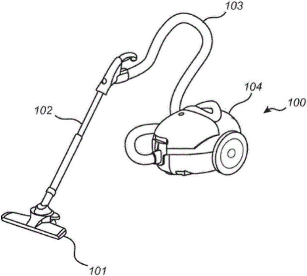
[0031] figure 1 A vacuum cleaner 100 is shown comprising a nozzle 101 according to an embodiment. The suction nozzle 101 may be connected to the main body 104 of the vacuum cleaner 100 via a tube 102 and a hose 103 .

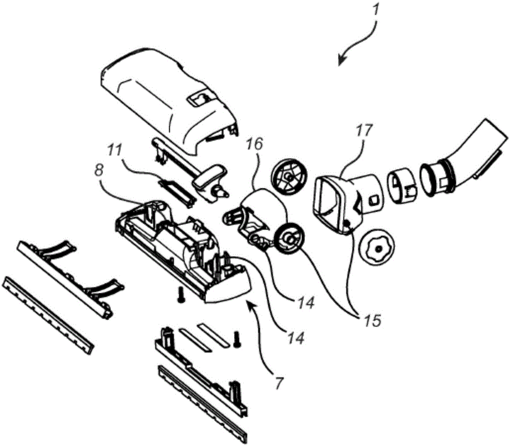
[0032] refer to figure 2 A vacuum cleaner nozzle according to an embodiment will be described. figure 2 is an exploded view of a suction nozzle 1 comprising several rigid parts 7, 16, 17 interconnected to each other by one or more joints 14, 15 (or hinged connections). The suction nozzle 1 comprises a suction disc 7 connected to an intermediate part 16 by means of a hinged connection 14 , whereby the suction disc 7 is arranged to pivot relative to the intermediate part 16 . The nozzle 1 also comprises an outlet part 17 adapted to be coupled (directly or indirectly) to a hose of the vacuum cleaner and connected to the intermediate part 16 via the hinged connection 15 . Thus, the three rigid parts 7, 16, 17 may be arranged to pivot at least slightly relative...


PUM


Abstract

The present disclosure relates to a nozzle for a vacuum cleaner. The nozzle comprises a suction plate (7) which comprises an air duct (12) having a vertical end portion (3) arranged to extend towards a suction opening. The suction plate comprises a sealing edge (18) extending along at least a portion of the suction opening, wherein a first portion (5a) of the sealing edge is arranged to be displaced in a natural movement direction (20) of the nozzle with respect to a second portion (6a) of the sealing edge. Further, the end portion of the air duct is arranged to be constantly flared and / or straight in the vertical direction towards and up to the first portion of the sealing edge and the second portion of the sealing edge. The present configuration of the suction plate facilitates manufacturing of the nozzle.

Description

technical field [0001] The present invention generally relates to the field of vacuum cleaner nozzles having a sealing edge at the suction opening. Background technique [0002] It is generally known that vacuum cleaner nozzles include a plurality of fittings at the connection between the outlet of the nozzle and the extension tube and / or suction hose in order to improve performance on uneven and soft surfaces. The multiple connections make the vacuum cleaner nozzle adaptable to such surfaces, picking up more dirt when the hose and vacuum cleaner nozzle are working over floors or carpets. WO 02 / 26097 discloses a vacuum cleaner nozzle which is pivotally mounted relative to the nozzle outlet so that movement of the vacuum cleaner nozzle in forward and backward directions alternately causes the two working edges ( or a sealing edge, which is arranged to restrict the flow of air from the area surrounding the active suction zone of a vacuum cleaner nozzle on a soft surface) clos...

Claims


Application Information

Patent Timeline
Patent Type & Authority Applications(China)
IPC IPC(8): A47L9/06
CPCA47L9/0666A47L9/02
Inventor J·瓦德柳斯
Owner AB ELECTROLUX
Features
  • R&D
  • Intellectual Property
  • Life Sciences
  • Materials
  • Tech Scout
  • Unparalleled Data Quality
  • Higher Quality Content
  • 60% Fewer Hallucinations
Learn More