throw device

A technology of center pipe and casing, which is applied in the direction of wellbore/well components, earthwork drilling and production, etc., can solve problems such as inability to carry out cementing operations, and achieve the effects of avoiding oil wells from becoming obsolete, facilitating popularization and application, and eliminating obstacles

Active Publication Date: 2019-04-05
CHINA PETROLEUM & CHEM CORP +1
View PDF8 Cites 0 Cited by
  • Summary
  • Abstract
  • Description
  • Claims
  • Application Information

AI Technical Summary

Problems solved by technology

However, this method of rotating resistance will cause the release device to be completed ahead of time before the liner hanger is delivered to the designed position, making subsequent cementing operations impossible

Method used


Image

  • throw device
  • throw device
  • throw device

Examples


Embodiment Construction

[0024] The present invention will be further described below with reference to the accompanying drawings.

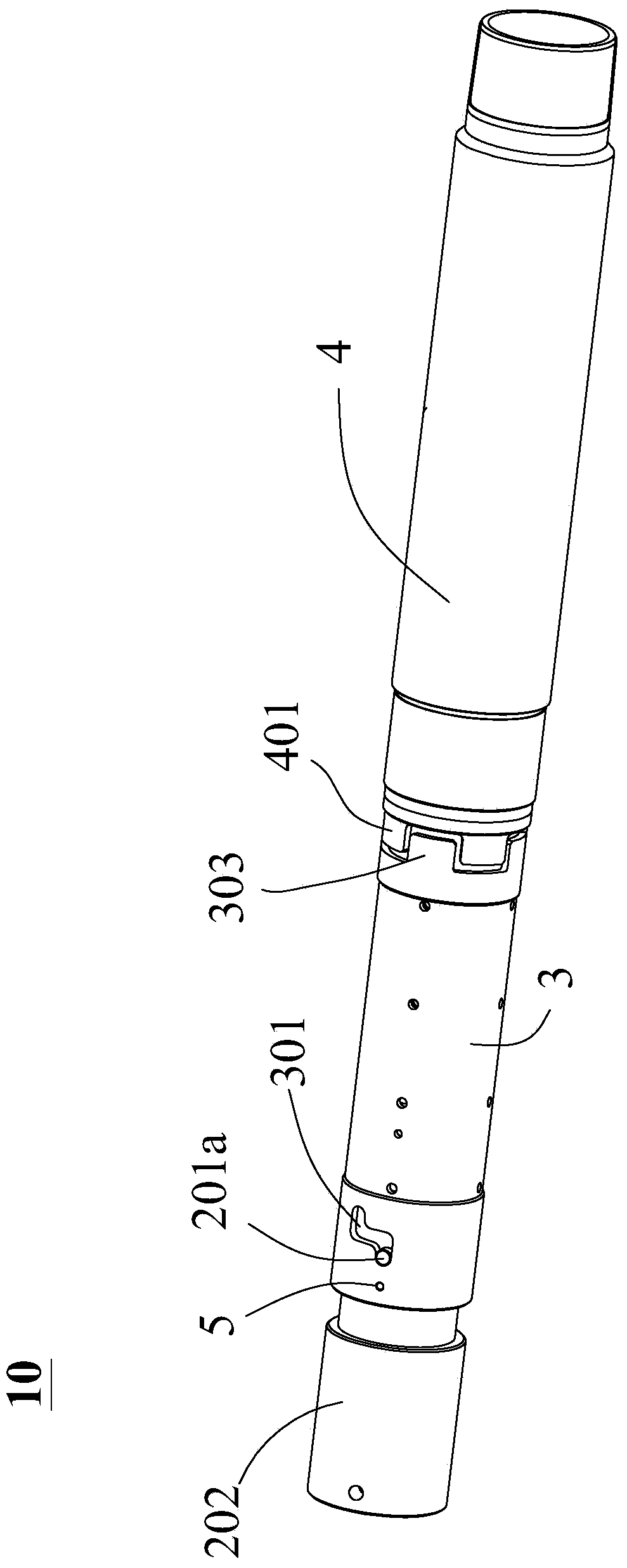
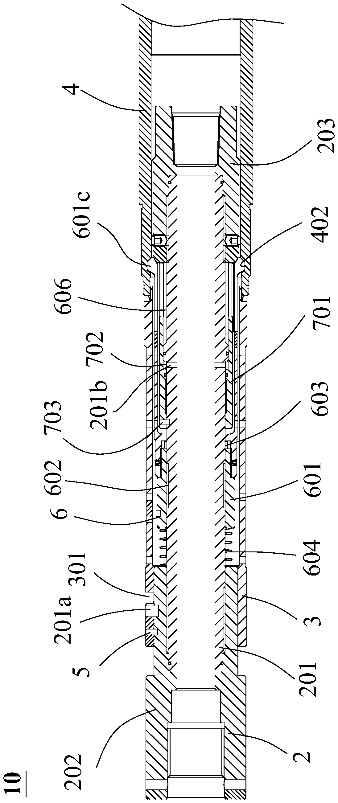
[0025] The main purpose of the throwing device according to the present invention is to throw the tailpipe hanger into the set position. like figure 1 and 2 As shown, the hand throwing device 10 according to the present invention includes a core tube assembly 2 . The core tube assembly 2 includes a central tube 201 , and tubular joints 202 and support members 203 respectively disposed at both ends of the central tube 201 . Preferably, the pipe joint 202 and the support member 203 are respectively sleeved outside the upstream end and the downstream end of the central pipe 201 through a threaded structure. The tubular joint 202 includes a transmission member 201a provided on the outer wall of its body. The transmission member 201a is preferably a pin, for example, fixed in the body of the pipe joint 202 through a threaded structure.

[0026] According to the present i...


PUM


Abstract

The invention relates to a releasing device which comprises the components of a core pipe assembly that comprises a central pipe and a pipe type joint that are in butt-joint with each other, wherein the outer circumferential wall of the pipe type joint is provided with a transmission member; a first outer sleeve which sleeves the central pipe and the pipe type joint and is fixed with the pipe type joint through a shearing component, wherein the first outer sleeve comprises a rotation facilitating track hole which is arranged on the circumferential wall; a second outer sleeve which sleeves the central pipe and is connected with the first outer sleeve through a plug-in rotation facilitating structure; and a snapping assembly which is used for preventing disengagement of the second outer sleeve from the first outer sleeve in an axial direction, wherein the core pipe assembly is constructed for causing failure of the shearing component under the function of an external force and driving the transmission member to move along the extending direction of the rotation facilitating track hole of the first outer sleeve so that a restriction to the second outer sleeve is released when the second outer sleeve functions on the snapping assembly. The releasing device according to the invention can effectively prevent an over-early releasing problem.

Description

technical field [0001] The invention relates to the technical field of cementing in oil and gas fields, in particular to a hand-throwing device used for downhole. Background technique [0002] In the cementing process, the hand drop device is one of the key components of the rotary liner hanger. Whether the dropping device can smoothly send the liner to the design position in the well, whether it can drop the liner after hanging, and whether it can rotate the liner smoothly during the liner entry and cementing process, is to test its performance. key indicators. [0003] At present, the existing hand-dropping devices all use the reverse buckle forward to turn the hand-dropping device. When the hand-throwing device is lost, the nut of the hand-throwing device needs to be driven to rotate forward by rotating the drilling tool in a forward direction, so as to release the threaded connection between it and the tail pipe hanger, and realize the hand-throwing operation. After t...

Claims


Application Information

Patent Timeline
Patent Type & Authority Patents(China)
IPC IPC(8): E21B23/00
Inventor 阮臣良李夯马兰荣郭朝辉侯乃贺张瑞
Owner CHINA PETROLEUM & CHEM CORP
Why Eureka
Try Eureka