Temporary train speed limiting device

A technology of limiting device and speed limit, applied in the direction of vehicle control route device, control drive, electric vehicle, etc., to achieve the effect of reliable and safe cost advantage

Active Publication Date: 2020-01-24
NIPPON SIGNAL CO LTD
View PDF6 Cites 0 Cited by
  • Summary
  • Abstract
  • Description
  • Claims
  • Application Information

AI Technical Summary

Problems solved by technology

Therefore, countermeasures such as setting up temporary speed limit ground beacons at positions before entering the construction area cannot be taken.

Method used


Image

  • Temporary train speed limiting device

Examples


Embodiment Construction

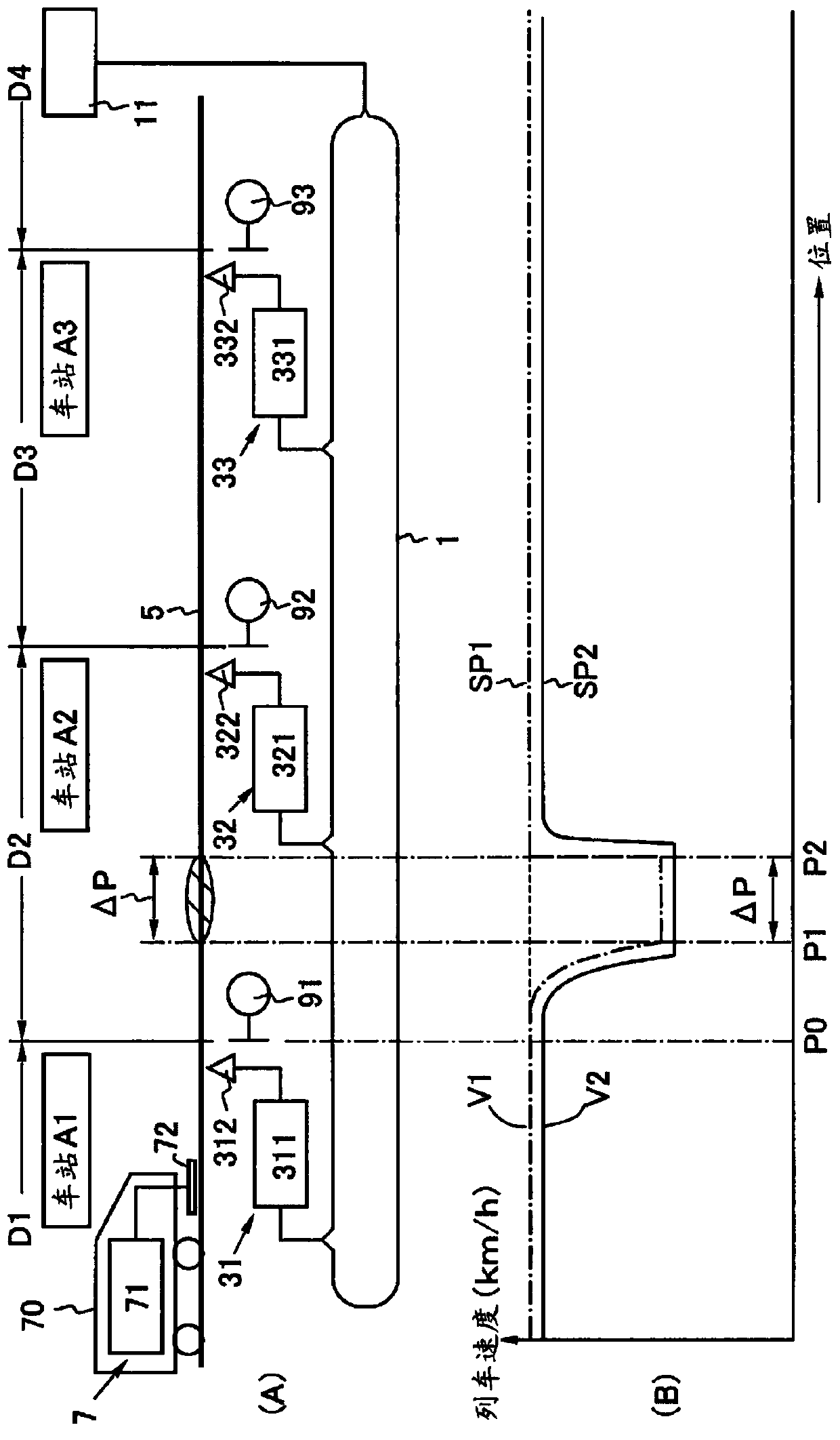
[0020] Referring to the drawings, the train speed temporary limiting device of the present invention includes an information transmission path 1 , ground devices 31 to 33 , and an in-vehicle device 7 . The information transmission path 1 is laid continuously along the line 5 across a plurality of train control sections D1 to D4, and transmits a temporary instruction indicating that the train speed should be temporarily limited in a certain area ΔP of the train control sections D1 to D4. Speed ​​limit information. exist figure 1 In the case of (A), the area ΔP is located in the train control section D2 adjacent to the train control section D1, and is located between the points P1 and P2 with the boundary between the train control sections D1-D2 as the reference point P0.

[0021] The information transmission path 1 can be constituted by an already established LAN that transmits operation management information. The established LAN that transmits the operation management infor...


PUM


Abstract

The present invention provides a train speed that can reliably and safely implement temporary train speed restrictions required for facility works such as rapid deterioration of weather conditions and line renovations while maintaining the cost advantage of utilizing the advantages of the point-type ATP system. Temporary restraint device. The train speed temporary limiting device includes an information transmission path (1), ground devices (31)-(33) and a vehicle-mounted device (7). The information transmission path (1) is laid along a line (5) across a plurality of train control sections (D1) to (D4). The information transmission path transmits temporary speed limit information indicating that the train speed should be temporarily limited in a certain area (ΔP) of the train control section. The ground device is installed in the train control section, and transmits the temporary speed limit information supplied from the information transmission path.

Description

technical field [0001] The present invention relates to a train speed temporary limiting device for temporarily limiting the train speed. Background technique [0002] Conventionally, an ATC (Automatic Train Control: Automatic Train Control) device, a CBTC (Communications-Based Train Control: Communication-Based Train Control) system, and the like are known as train control technologies. In addition, a point-type ATS-P (Automatic Train Stop system-Pattern: Automatic Train Stop System Pattern) system (hereinafter, simply referred to as a point-type ATP system) having a cost advantage over these systems is also known. [0003] In the point-type ATP system, for example, as disclosed in Patent Document 1, ground beacons are installed at predetermined intervals along a route on which a train travels, and speed limit information is transmitted by these ground beacons. By receiving this information with the in-vehicle device, a speed pattern based on the speed limit of the train i...

Claims


Application Information

Patent Timeline
Patent Type & Authority Patents(China)
IPC IPC(8): B60L15/40B61L3/12B61L23/14
CPCB61L3/008B61L3/121B61L3/125B61L15/0027B61L15/0072B61L2205/00B61L27/70
Inventor 明庆健一栗田晃
Owner NIPPON SIGNAL CO LTD
Why Eureka
Try Eureka