
Determining method of sounding rocket aerodynamic configuration optimization objective function

A technology for optimizing objective functions and sounding rockets, applied in electrical digital data processing, special data processing applications, instruments, etc., can solve the problems of not being able to maximize the height of the ballistic vertex, high subjectivity and arbitrariness, and long time consumption

Active Publication Date: 2015-12-16
NAT UNIV OF DEFENSE TECH
View PDF1 Cites 2 Cited by
  • Summary
  • Abstract
  • Description
  • Claims
  • Application Information

AI Technical Summary

Problems solved by technology

At present, there are mainly two methods for determining the objective function of the aerodynamic shape design optimization of sounding rockets at home and abroad: one is to combine ballistic simulation, and take the ballistic characteristic data such as the highest height of the ballistic apex as the objective function; Objective function, the shape optimization result obtained by the former can maximize the height of the ballistic vertex and improve the performance of the rocket, but a single objective function calculation process needs to complete the calculation of aerodynamic characteristics and ballistic integration in sequence, which takes a long time; the acquisition of the latter objective function only involves The calculation of aerodynamic characteristics is relatively convenient, but the selection of weighting coefficients is relatively subjective and arbitrary, and cannot maximize the height of the ballistic apex

Method used


Image

  • Determining method of sounding rocket aerodynamic configuration optimization objective function
  • Determining method of sounding rocket aerodynamic configuration optimization objective function
  • Determining method of sounding rocket aerodynamic configuration optimization objective function

Examples


Embodiment Construction

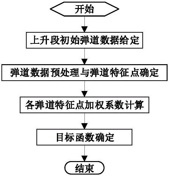
[0046] The flow chart of the method for determining the objective function of the aerodynamic shape optimization of the sounding rocket proposed by the present invention is as follows: figure 2 shown. The present invention will be further described below in conjunction with the accompanying drawings to the specific embodiments of the present invention.

[0047] Step 1: Give the initial trajectory data of the ascent stage of the rocket

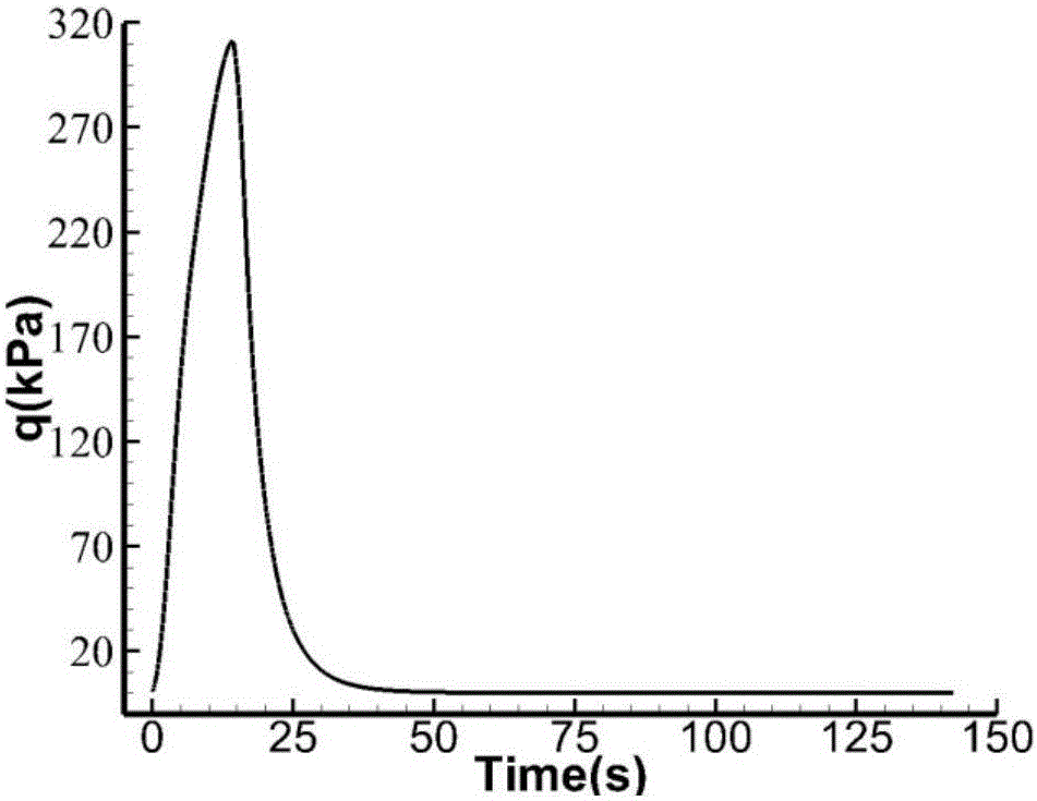
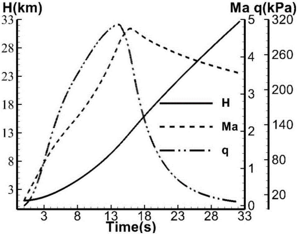
[0048] Given the initial trajectory data of the ascent stage of the rocket including time, height, Mach number, angle of attack, dynamic pressure and other parameters, taking a certain type of single-stage uncontrolled meteorological rocket as an example, the dynamic pressure of the ascent stage varies with time as follows: figure 1 shown.

[0049] Step 2: Preprocessing the initial ballistic data to determine the ballistic feature points

[0050] Let time t c Satisfies the following formula:

[0051] ∫ 0 ...


PUM


Abstract

In order to overcome the defects of the existing target function determining method in the aspects of optimization efficiency and optimization result in the sounding rocket aerodynamic configuration design optimization process, the invention provides a determining method of a sounding rocket aerodynamic configuration optimization objective function. By using the minimum momentum loss of aerodynamic resistance along the trajectory as the starting point, the invention provides the determining method of the sounding rocket aerodynamic configuration optimization objective function. The determining method comprises the following steps of: (1) giving initial trajectory data at the rocket ascending stage; (2) performing initial trajectory data preprocessing, and determining trajectory feature points; (3) calculating the weighting coefficient of each feature point; and (4) using the minimum weighting resistance coefficient of the trajectory feature points as the sounding rocket aerodynamic configuration optimization objective function. The determining method has the advantages that the sounding rocket aerodynamic configuration optimization efficiency is obviously improved; the optimization result performance is improved; and the determining method is applicable to the appearance design of various sounding rockets in each design stage, and can be popularized and applied to the aerodynamic configuration optimization objective function determination of other aircraft.

Description

technical field [0001] The invention belongs to the field of aircraft shape design optimization, and in particular relates to an objective function determination method for sounding rocket aerodynamic shape optimization. Background technique [0002] Sounding rockets are an indispensable and effective tool for space exploration and scientific experiments. Since the first sounding rocket WacCorporal was launched by the US Jet Propulsion Laboratory (JPL) in 1945, humans have launched thousands of sounding rockets. A large number of application results have been obtained in the fields of detection, space environment detection, microgravity experiments, biological experiments, and space new technology verification. With the rapid development of near-space vehicles and the continuous progress of space science research, the use mode of sounding rockets will continue to expand, and they will be more and more widely used in the fields of space exploration and scientific experiments....

Claims


Application Information

Patent Timeline
IPC IPC(8): G06F17/50
Inventor 江振宇彭科张士峰胡凡向敏
Owner NAT UNIV OF DEFENSE TECH
Learn More