A kind of anti-creep expansion instrument

A technology of dilatometer and creep, applied in the field of anti-creep dilatometer, can solve problems such as creep deformation in the measurement direction, achieve the effect of ensuring measurement accuracy and overcoming high temperature creep

Inactive Publication Date: 2018-03-27
HENAN UNIV OF SCI & TECH
View PDF8 Cites 0 Cited by
  • Summary
  • Abstract
  • Description
  • Claims
  • Application Information

AI Technical Summary

Problems solved by technology

[0003] The purpose of the present invention is to provide an anti-creep dilatometer to solve the problem in the prior art that the sample is prone to creep deformation in the measurement direction due to the clamping force under high temperature conditions.

Method used


Image

  • A kind of anti-creep expansion instrument
  • A kind of anti-creep expansion instrument

Examples


Embodiment Construction

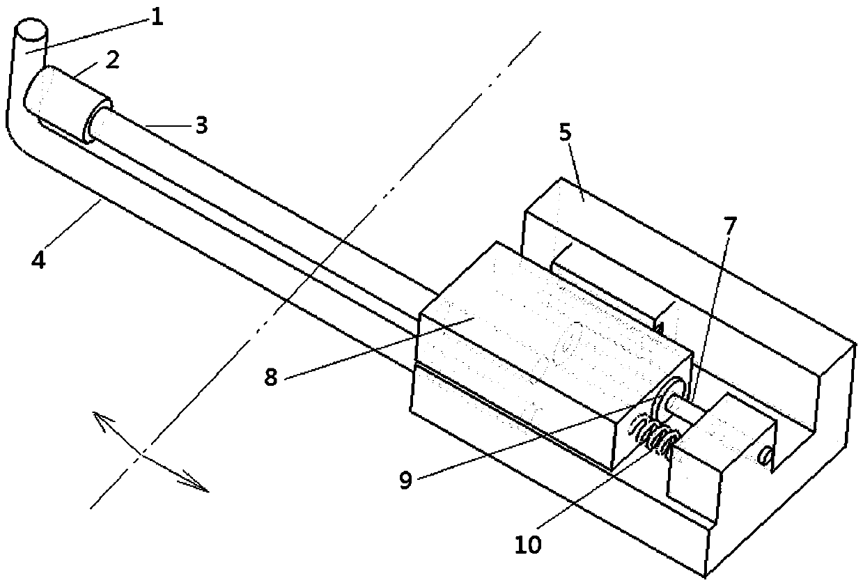
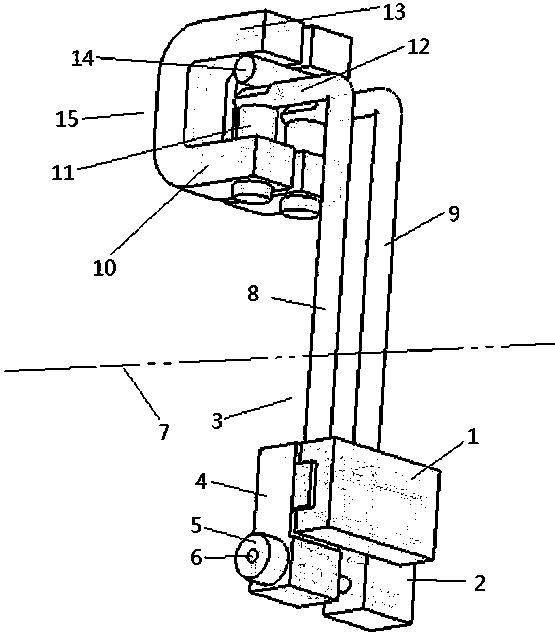
[0013] An example of an anti-creep dilatation instrument figure 2 Shown: It includes a left bracket 4 and a right bracket 2 that can move relatively and oppositely in the left and right directions. The left and right brackets are provided with linear bearings 1 for the left and right brackets to move in the left and right directions. The left and right brackets A displacement sensor for measuring the relative displacement of the left and right brackets is also arranged on the top, the displacement sensor includes a sensor coil 5 arranged on the left bracket and an iron core rod 6 arranged on the right bracket, and the iron core rod 6 passes through the sensor coil Among them, the axes of the iron core rod and the sensor coil extend along the left and right directions. The left bracket 4 is provided with a left clamping assembly for clamping and fixing a sample deformable in the left and right directions, and the right bracket is provided with a right clamping assembly 9 for c...


PUM


Abstract

The invention relates to an anti-creep dilatometer, which comprises a left bracket and a right bracket which can move relative to each other or move opposite to each other in the left and right directions, and the left and right brackets are provided with displacement sensors for measuring the displacement of the right bracket relative to the left bracket, The left bracket is provided with a left clamping assembly for clamping and fixing the sample whose displacement measurement direction is the left and right directions, and the right bracket is provided with a right clamping assembly for clamping and fixing the sample. The direction of the clamping force of the clamping assembly on the sample is perpendicular to the left-right direction. The invention solves the problem in the prior art that the sample is prone to creep deformation in the measurement direction due to the clamping force under high temperature conditions.

Description

technical field [0001] The invention relates to an anti-creep expansion instrument for detecting the expansion of a sample. Background technique [0002] There are many kinds of traditional contact dilatometers, one of the more common dilatometers is the L-rod dilatometer such as figure 1 Shown: including a bracket 5, the bracket is provided with an L-shaped support rod 4, and a slider 8 is installed on the bracket to guide and move along the front and rear directions. The foot part 1 of the stick cooperates to clamp and fix the two ends of the sample 2. A spring 10 is arranged between the bracket 5 and the slider 8 to apply a forward force to the slider. A sensor coil 9 is arranged on the bracket. The slide block is provided with left and right iron core rods that pass through the sensor coil 9 . When in use, the sample is placed between the straight support rod and the foot of the L-shaped support rod. Under the action of the spring, the feet of the straight support rod ...

Claims


Application Information

Patent Timeline
Patent Type & Authority Patents(China)
IPC IPC(8): G01N25/16
Inventor 周旭东刘香茹毛爱霞琚伟伟李小红
Owner HENAN UNIV OF SCI & TECH
Why Eureka
Try Eureka