
System and method for measuring and mapping a surface relative to a reference

Active Publication Date: 2010-05-27
METSO OUTOTEC (FINLAND) OY
View PDF17 Cites 69 Cited by
  • Summary
  • Abstract
  • Description
  • Claims
  • Application Information

AI Technical Summary

Benefits of technology

[0022]It is an object of the present invention to ameliorate, mitigate or overcome, at least one of the aforementioned problems associated with prior art mill liner measurement or to at least provide the public with a useful choice in an alternative system for mill liner measurement.

Problems solved by technology

Consequently, the liner takes up wear in preference to the base surface, and is replaced from time to time in lieu of replacing the base surface, which may be more difficult or more expensive to replace.
Assessing the degree of wear of a surface, be it with or without a liner, is difficult or time consuming in certain environments such as where the surface is disposed internally within a cavity or compartment of a body, and especially where that body is rotatable.
Conventional measurement tools are often inadequate to perform the task, either with respect to the precision of measurement, safety of performing the task, or economic factors associated with downtime of commercial use of the body whilst the measurement task is undertaken.
Naturally, mill liners wear through erosion.
Whilst good liner design can enhance milling efficiency, worn liners have a detrimental effect on milling performance and energy efficiency.
Replacing mill liners requires significant mill downtime which is undesirable from an economic point of view.
The downtime is attributable to the time taken to assess the thickness of the liner, and the considerable time needed to replace the liner.
The problem with this approach is the time consumed in decontaminating the mill, and further, the inaccuracy of relying on the human eye to determine the thickness of an object of which the depth dimension is invisible.
As the liner wears faster than the protruding nail, inspection of the length of protrusion provides an indication of wear.
The problem with this method is that it is time consuming in terms of mill downtime while decontamination procedures and measurement processes are executed, and further, the inaccuracy of estimating the thickness from measurements of the nail, which itself is subject to wear, against the liner wear.
Further, the comparative sparsity of measurement coverage of the liner is also a problem.
The problem with this approach is that it does not directly measure the mill liner thickness.
There are several problems with ultrasonic thickness gauging.
Secondly, temperature alters sound velocity, and hence calibration is always needed to guarantee accurate readings.
Thirdly, it is slow, as each point must be recorded manually.
Fourthly, it is difficult to accurately assess liner wear due to the need to ensure that the sensor measurement tool is orthogonal to the mill shell, and the practical difficulty in achieving this.

Method used


Image

  • System and method for measuring and mapping a surface relative to a reference
  • System and method for measuring and mapping a surface relative to a reference
  • System and method for measuring and mapping a surface relative to a reference

Examples


Embodiment Construction

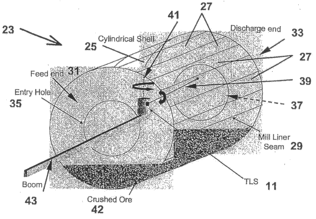
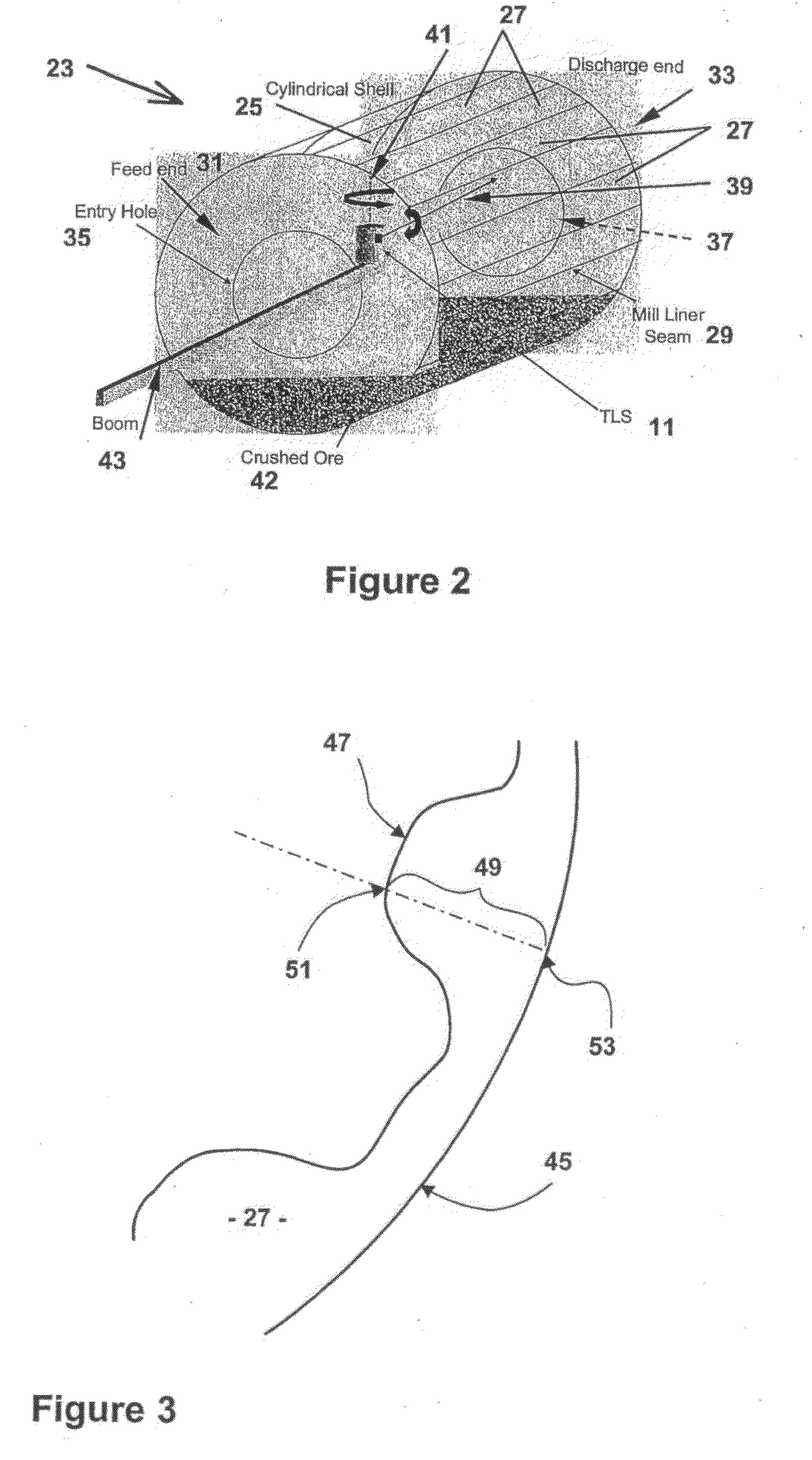
[0068]The best mode for carrying out the invention will now be described with reference to one specific embodiment thereof. The description of the specific embodiment makes reference to the accompanying drawings. Accordingly reference numerals referred to herein are used in the drawings to show the corresponding feature described in the embodiment.

[0069]The embodiment is directed towards a system and method specifically adapted for mapping and measuring the thickness of a mill liner provided on the inner surface of a mill for grinding rock and ore therein. The liner is provided to protect the inner surface of the shell of the mill and to assist with the comminution process performed by the mill.

[0070]As previously discussed, replacing mill liners is a costly, but necessary, task associated with the operation of a mill.

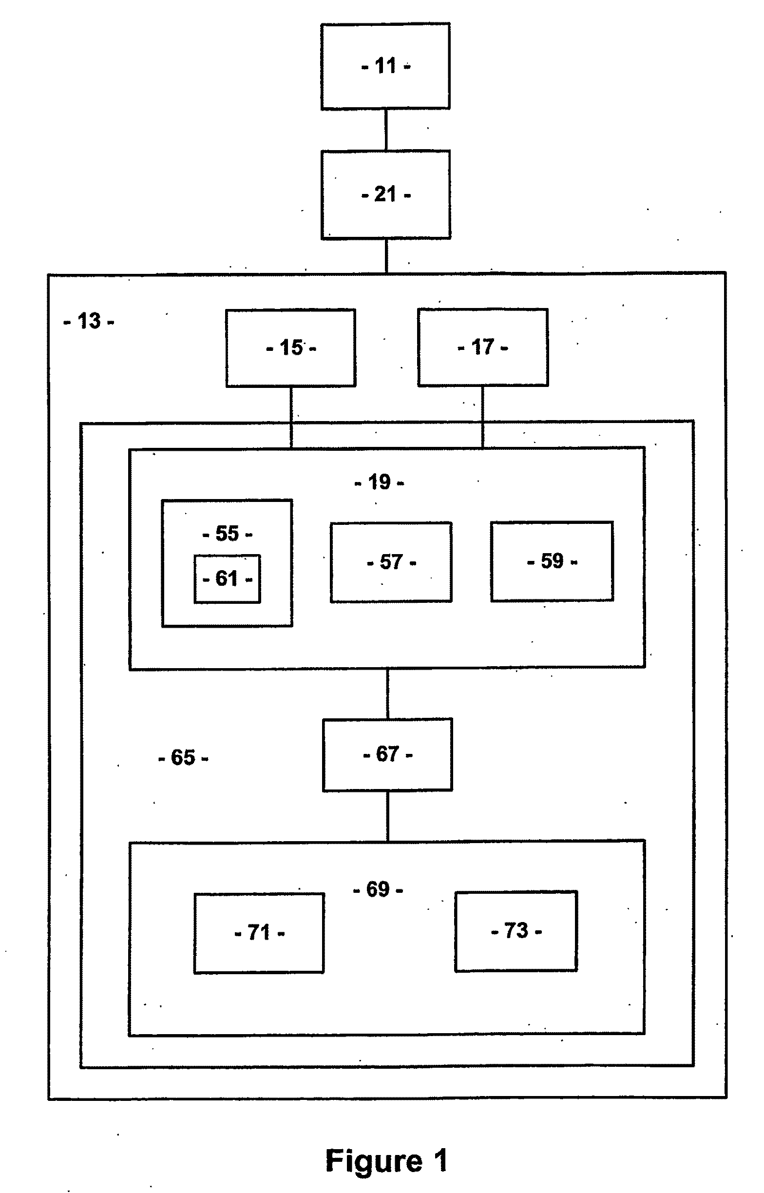
[0071]As shown in FIG. 1, the system essentially comprises:[0072]scanning means in the form of a terrestrial laser scanner 11;[0073]computer 13 including:[0074]data ac...


PUM


Abstract

A system and method for measuring the displacement of a surface relative to a base reference, as well as for mapping the displacement of the surface relative to the base reference. A laser scanner generates point cloud data in respect of a measure of the spatial orientation of a distal surface relative to a reference point to define a three-dimensional image of the surface. Reference data is stored in respect of the spatial orientation of a base reference relative to the surface. processing means to process said point cloud data and said base reference data to determine the relative displacement of said surface with respect to said base reference. A system comprising: data processing means to obtain point cloud data defining a surface in a co-ordinate system coinciding with a base reference and to generate displacement data in respect of the displacement between each point of said point cloud and a related point of said base reference; comparison means to compare the displacement data against a prescribed threshold; and display means to graphically display the result of the comparison.

Description

FIELD OF THE INVENTION[0001]The present invention relates to scanning systems and methods for examining surfaces of bodies subject to wear or change over time. The invention has particular, although not exclusive, utility for measuring surfaces and comparing them against historical data to determine whether the surface needs repair or replacement.[0002]Throughout the specification, unless the context requires otherwise, the word “comprise” or variations such as “comprises” or “comprising”, will be understood to imply the inclusion of a stated integer or group of integers but not the exclusion of any other integer or group of integers.BACKGROUND ART[0003]The following discussion of the background art is intended to facilitate an understanding of the present invention only. The discussion is not an acknowledgement or admission that any of the material referred to is or was part of the common general knowledge as at the priority date of the application.[0004]In many applications, it is...

Claims


Application Information

Patent Timeline
IPC IPC(8): G06F15/00G06F17/18
CPCB02C4/32G01B11/24G01B11/0616
Inventor STEWART, MICHAEL PAULLICHTI, DEREKFRANKE, JOCHEN
Owner METSO OUTOTEC (FINLAND) OY
Learn More