
Image edge modification method and edge modification device

A modification method and edge technology, applied in the field of image processing, can solve the problems affecting the display effect, achieve the effect of improving the display effect, enhancing the contrast, and avoiding the generation of color borders

Active Publication Date: 2018-10-30
XIAMEN TIANMA MICRO ELECTRONICS +1
View PDF11 Cites 0 Cited by
  • Summary
  • Abstract
  • Description
  • Claims
  • Application Information

AI Technical Summary

Problems solved by technology

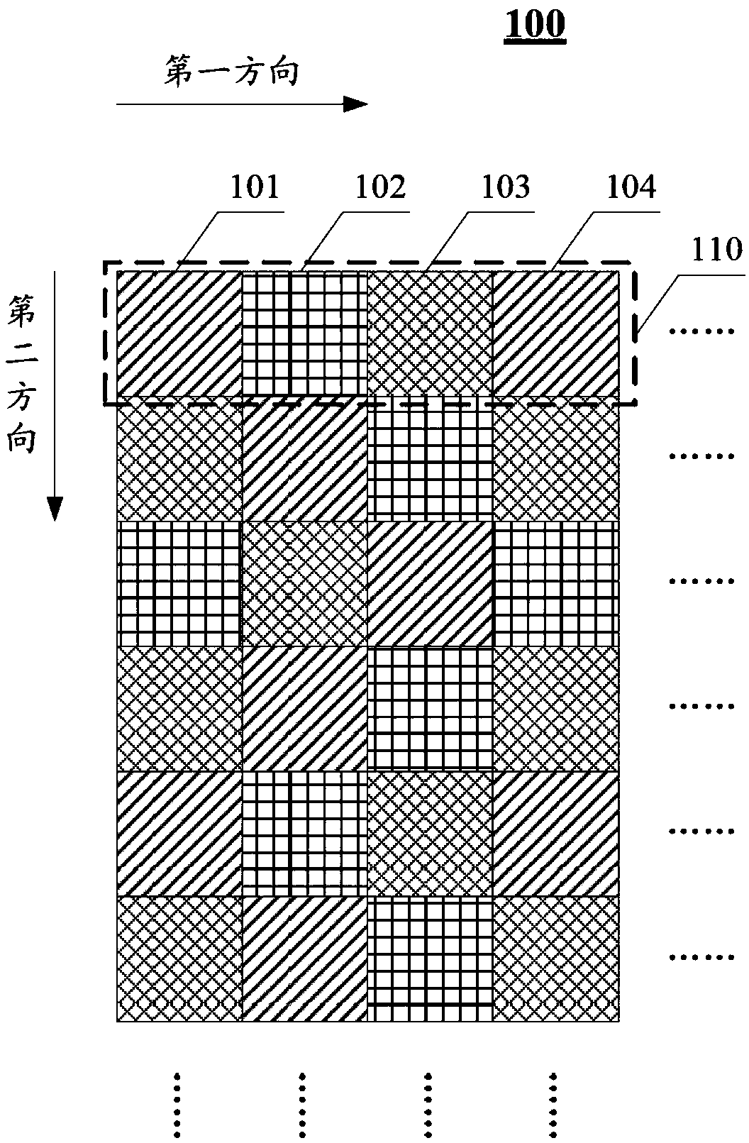
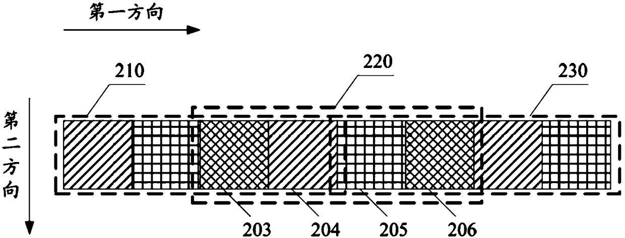
After edge processing, in the minimum display unit 410' corresponding to the minimum display unit 410 before processing, the luminance ratio of each color sub-pixel in 420' and 430' adjacent to the minimum display unit 410' representing the bright bottom dark edge Changes have occurred, which will lead to the appearance of color edges and affect the display effect

Method used


Image

  • Image edge modification method and edge modification device
  • Image edge modification method and edge modification device
  • Image edge modification method and edge modification device

Examples


Embodiment Construction

[0025] The application will be further described in detail below in conjunction with the accompanying drawings and embodiments. It should be understood that the specific embodiments described here are only used to explain related inventions, rather than to limit the invention. It should also be noted that, for ease of description, only parts related to the invention are shown in the drawings.

[0026] It should be noted that, in the case of no conflict, the embodiments in the present application and the features in the embodiments can be combined with each other. The present application will be described in detail below with reference to the accompanying drawings and embodiments.

[0027] see Figure 5 As shown, it is a schematic flowchart 500 of an image edge modification method according to an embodiment of the present application.

[0028] Specifically, in step 510, a central pixel in the image is selected, wherein the central pixel is any pixel in the image representing...


PUM


Abstract

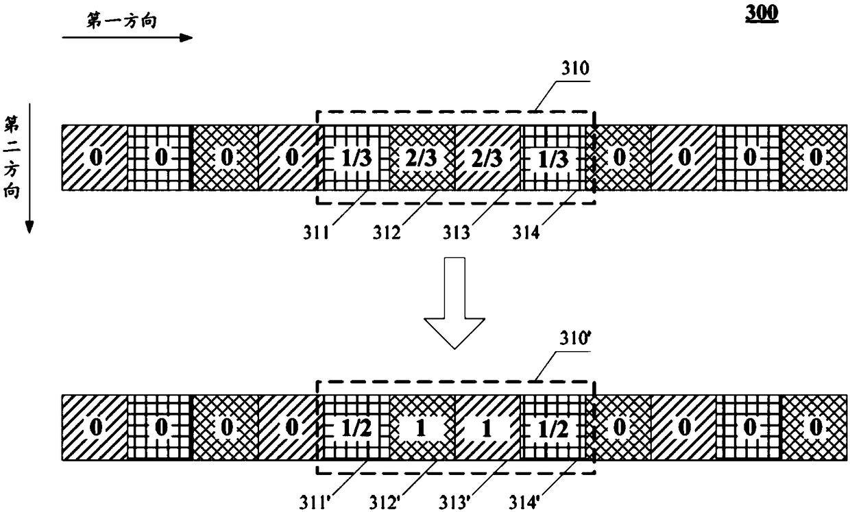
The invention discloses a method and a device for image rim modification. The method disclosed by the invention comprises steps of choosing a center pixel of an image, wherein the center pixel is any pixel representing the rim of the image in the image, obtaining the brightness value of a center pixel and an adjacent pixel adjacent with the center pixel, and performing brightness switching on the adjacent pixel based on predetermined sub-pixel shared mode. According to the application scheme, the brightness switching is performed on the pixels representing the rim of the image before SPR rendering so as to enhance the contrast effect between the image rim and the image background.

Description

technical field [0001] The present disclosure generally relates to image processing technology, and specifically relates to an image edge modification method and an edge modification device. Background technique [0002] Currently, consumers are gradually improving the display quality of portable mobile terminals, and the design and development of high PPI (Pixel per Inch, pixels per inch) display has become a hot spot in the display industry. At this stage, products above 800PPI have appeared, but the subsequent low aperture ratio and extremely high process requirements have made it difficult to improve the yield of high PPI products, so it is also difficult to reduce the cost. [0003] In this context, SPR (Sub Pixel Rendering, sub-pixel rendering) technology emerged as the times require, providing a shortcut for the marketization of high-PPI technology. The so-called SPR technology refers to the low-PPI pixel array arranged in a reasonable pixel order and sub-pixel rende...

Claims


Application Information

Patent Timeline
Patent Type & Authority Patents(China)
IPC IPC(8): G09G5/10
Inventor 方丽婷张沼栋
Owner XIAMEN TIANMA MICRO ELECTRONICS
Learn More