A Plane Rolling Cutter for Constant Distance Rolling

A rolling tool and tool technology, applied in the field of flat rolling tools, can solve the problems of low machining accuracy, difficult to control rolling allowance, large rolling allowance, etc., and achieve high machining accuracy, improved effect, and constant rolling force. Effect

Active Publication Date: 2018-01-05
ZHEJIANG UNIV OF TECH
View PDF8 Cites 1 Cited by
  • Summary
  • Abstract
  • Description
  • Claims
  • Application Information

AI Technical Summary

Problems solved by technology

[0004] In order to overcome the problem of unsatisfactory processing effect and low machining accuracy caused by the difficulty in controlling the rolling allowance and excessive rolling allowance in the existing chip-free machining

Method used


Image

  • A Plane Rolling Cutter for Constant Distance Rolling

Examples


Embodiment Construction

[0016] The present invention will be further described below in conjunction with the drawings.

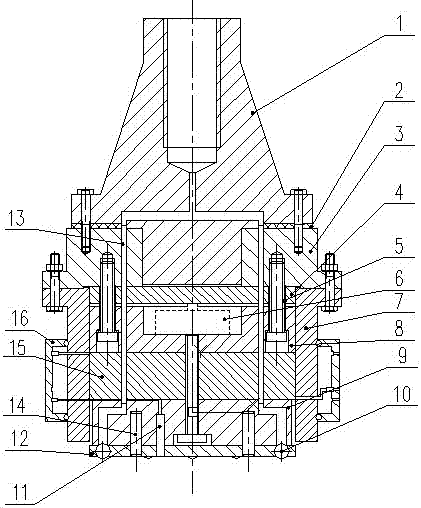
[0017] Referring to the drawings, a flat rolling tool for constant distance rolling includes a handle portion and a tool body. The handle portion includes a handle 1 and a handle connecting block 3, the handle 1 and the knife The shank connecting block 3 is connected. An oil sealing gasket 2 is provided between the tool shank 1 and the tool shank connecting block 3. The tool body includes a tool connection cylinder 7 and a ball assembly located at the lower part of the tool connection cylinder. The connecting block 3 is connected to the upper end of the cutter connecting cylinder 7, and the cutter body further includes a bearing plate 4, a force sensor 6, a sensor fixing seat 8, an electrostrictive block 15 and a supporting seat 9. The cutter connecting cylinder 7 The load-bearing plate 4, the force sensor 6, the sensor fixing seat 8, the electrostrictive block 15, the support seat 9 ...


PUM


Abstract

The invention discloses a planar rolling cutter with the constant distance rolling function. The planar rolling cutter comprises a shank part and a cutter body, wherein the shank part comprises a shank and a shank connecting block which are connected; an oil seal gasket is arranged between the shank and the shank connecting block; the cutter body comprises a cutter connecting cylinder and a rolling ball component positioned at the lower part of the cutter connecting cylinder; the shank connecting block is connected with a force bearing plate in the cutter connecting cylinder; the force bearing plate is in clearance fit with a sensor fixing seat; a force sensor is mounted inside the sensor fixing seat; the sensor fixing seat is connected with an electrostriction block; the electrostriction block is fixedly connected with a support seat; the support seat is fixedly connected with the rolling ball component; a proximity switch is mounted at the bottom of the rolling ball component. According to the invention, the proximity switch is additionally mounted at the bottom of the cutter, so that the distance between the cutter and a workpiece is kept constant during the rolling process, and constant rolling pressure during the rolling process is guaranteed, so that the rolling effect is improved.

Description

Technical field [0001] The invention relates to the field of chipless processing, in particular to a flat rolling tool for constant distance rolling. Background technique [0002] The rolling method is a kind of chipless processing, which can not only achieve a high finish, but also improve the mechanical properties of the processed parts. The essence of the rolling method is to use high-hardness bladeless tools-steel balls or rollers to cause local high pressure on the processed surface. As the tool rolls along the surface to be processed, elastic-plastic deformation of the surface material is formed, so that the microscopic peaks left on the surface in the previous process are smoothed, and a certain thickness of strengthening layer is formed on the surface. Due to the smooth surface and increased hardness, the wear resistance and fatigue strength of the parts are greatly improved. [0003] The rolling cutter is connected to the main shaft of a milling machine and other machine...

Claims


Application Information

Patent Timeline
Patent Type & Authority Patents(China)
IPC IPC(8): B23P9/02
CPCB23P9/02
Inventor 朴钟宇周振宇郑波赵朦朦徐佳
Owner ZHEJIANG UNIV OF TECH
Why Eureka
Try Eureka