Combined puller

A puller and combined technology, which is applied in the fields of dismantling and installing tools and equipment maintenance, can solve problems such as difficult adjustment of the structure, and achieve the effect of a wide range of use

Active Publication Date: 2015-12-30
LAIWU IRON & STEEL GRP
View PDF7 Cites 0 Cited by
  • Summary
  • Abstract
  • Description
  • Claims
  • Application Information

AI Technical Summary

Problems solved by technology

[0003] The purpose of the present invention is to provide a combined puller to change the problem that the structure in the prior art is difficult to adjust to meet more demands

Method used


Image

  • Combined puller
  • Combined puller
  • Combined puller

Examples


Embodiment Construction

[0023] The present invention will be described in further detail below in conjunction with the accompanying drawings and specific embodiments.

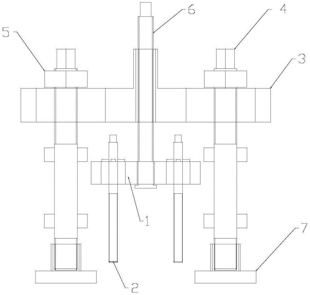
[0024] like figure 1 As shown, the embodiment of the present invention includes: a working plate 1, a pull plate bar 2, a frame plate 3, a frame bar 4, a nut 5, a lifting screw 6, and a powerful magnetic disk 7.

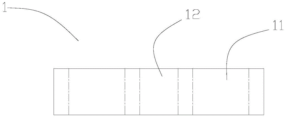
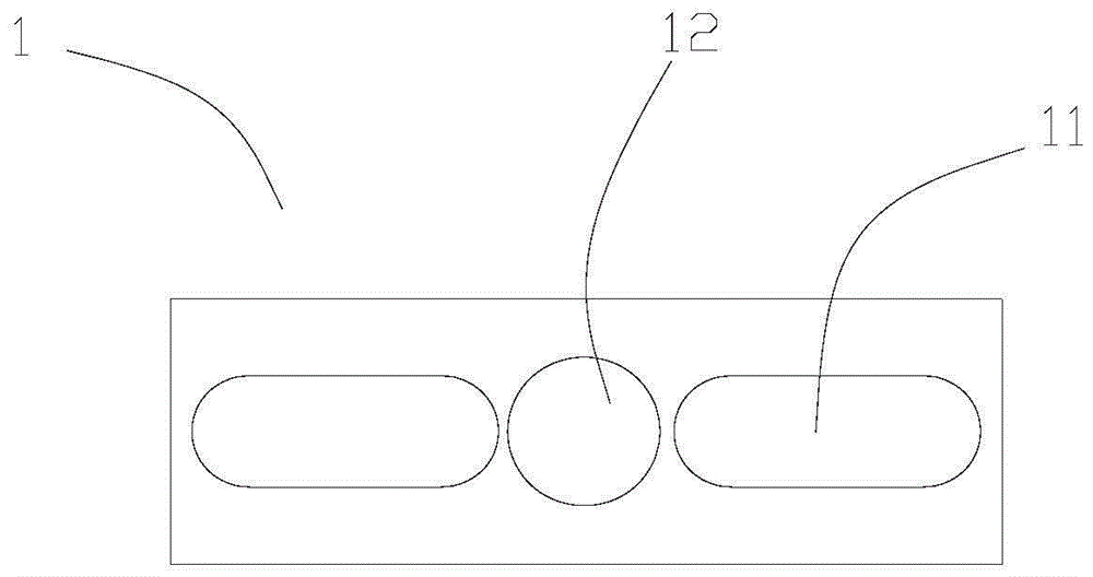
[0025] Specifically, as Figure 1-Figure 3 As shown, the working plate 1 is in the shape of a rectangular plate, on which a plurality of first elongated holes 11 and driving holes 12 are arranged, and the plurality of first elongated holes 11 are symmetrically distributed on both sides of the driving hole 12 . In the embodiment, the number of the first long holes 31 is two.

[0026] like figure 1 and Figure 4-Figure 5 As shown, the present embodiment includes two tie rods 2, but the number is not limited thereto and can be changed as required, but the number is consistent with the number of the first long holes. The up...


PUM


Abstract

The invention provides a combined puller which comprises a work plate, a plurality of plate pulling rods, a lifting lead screw, a frame plate and a plurality of frame rods, wherein the work plate is provided with a plurality of first long holes and a drive hole, and the first long holes are symmetrically distributed in the two sides of the drive hole; the upper ends of the plate pulling rods movably penetrate through the first long holes respectively and are provided with separating prevention structures for preventing the plate pulling rods from being separated from the first long holes; the bottom of the lifting lead screw is inserted into the drive hole in the work plate, the upper end of the lifting lead screw is provided with a rotating drive structure, and the bottom end of the lifting lead screw is provided with a plate pulling structure, so that when the rotating drive structure drives the work plate to move, the lifting lead screw is prevented from being separated from the work plate; the frame plate is provided with a plurality of second long holes and a lead screw hole, the second long holes are symmetrically distributed in the two sides of the lead screw hole, and the lifting lead screw is meshed into the lead screw hole; the upper ends of the frame rods movably penetrate through the second long holes respectively and are provided with positioning structures for stably arranging the frame plate at the upper end of the frame rods. The combined puller can be flexibly used in a narrow space and is simple in structure, flexible to operate and wide in use range.

Description

technical field [0001] The invention relates to the technical field of equipment maintenance, disassembly and installation tools, in particular to a combined puller. Background technique [0002] In the current industrial equipment, with the development of science and technology, the volume of the equipment is getting larger and higher, and the assembly precision is getting higher and higher. A large-scale equipment often needs to be assembled with a large number of parts, and the complexity of the equipment is getting higher and higher. When the equipment is When a certain part of the equipment is damaged, it is limited by the equipment space and installation location, and sometimes cumbersome disassembly is required to complete the replacement of equipment parts. However, the current puller has a single structure and solidification, and it is difficult to adjust it in time, which affects the work efficiency and the scope of use. Contents of the invention [0003] The pu...

Claims


Application Information

Patent Timeline
Patent Type & Authority Applications(China)
IPC IPC(8): B25B27/00
CPCB25B27/00
Inventor 李雪涛张戈
Owner LAIWU IRON & STEEL GRP
Why Eureka
Try Eureka