

Load bearing type jacking rod
A technology of ejector rod and rod body, applied in the direction of household components, other household appliances, household appliances, etc., can solve the problems of weak load capacity, easy to fall, single ejector rod structure, etc., and achieve the effect of enhancing the load capacity
Inactive Publication Date: 2015-12-30
CHANGZHOU HAIYING HARDWARE TECH
View PDF7 Cites 0 Cited by
- Summary
- Abstract
- Description
- Claims
- Application Information
AI Technical Summary
Problems solved by technology
The existing ejector rod has a single structure, and when it is necessary to hang objects, the load capacity is weak and it is easy to fall
Method used
View moreImage
Smart ImageViewing Examples

Examples
Embodiment Construction
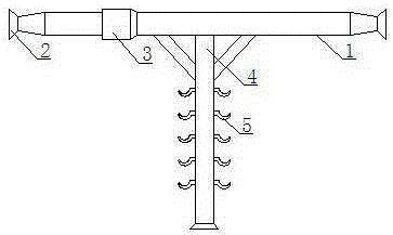
[0009] Such as figure 1 It is a structural schematic diagram of the present invention, a load-bearing ejector rod, including a rod body 1, a plug 2 and a lock nut 3, the plug 2 is connected to both ends of the rod body 1, the lock nut 3 is set in the middle of the rod body 1, and the rod body 1 A pillar 4 is vertically connected to the center of the bottom, and hooks 5 are evenly distributed on the pillar 4 .
[0010] Vertically connect the pillar 4 at the bottom center of the pole body 1, and evenly distribute the hooks 5 on the pillar 4 to form a composite suspension structure. The pillar 4 provides a strong support for the pole body 1, greatly enhancing the load-bearing capacity of the pole body 1.
Login to View More PUM
 Abstract
The invention relates to the technical field of a mechanical accessory, in particular to a load bearing type jacking rod. The load bearing type jacking rod comprises a rod body, jacking heads and a locking screw nut, wherein the jacking heads are connected with the two ends of the rod body; the locking screw nut is arranged in the middle part of the rod body in a sleeving way; a strut is vertically connected with the center of the bottom of the rod body; hooks are uniformly distributed on the strut. The strut is vertically connected with the center of the bottom of the rod body; the hooks are uniformly distributed on the strut; a composite hanging structure is formed; powerful support is provided for the rod body by the strut; the load bearing capability of the rod body is greatly enhanced.
Description
technical field [0001] The invention relates to the technical field of mechanical accessories, in particular to a load-bearing ejector rod. Background technique [0002] The ejector rod is a commonly used auxiliary device, which is used to support the gap between adjacent objects and play the role of applying pressure or hanging objects. The existing ejector rod has a single structure, and when an object needs to be suspended, the load-bearing capacity is weak and it is easy to fall. Contents of the invention [0003] In order to overcome the shortcomings of the existing ejector pins, which are weak in load capacity and easy to fall, the invention provides a load-bearing ejector pin. [0004] The technical solution adopted by the present invention to solve the technical problem is: a heavy-duty ejector rod, including a rod body, a plug and a lock nut, the plug is connected to both ends of the rod body, the lock nut is set in the middle of the rod body, and the center of t...
Claims
Login to View More Application Information
Patent Timeline
 IPC IPC(8): F16M13/00A47G29/00
Inventor朱海涛
OwnerCHANGZHOU HAIYING HARDWARE TECH