LED (light-emitting diode) down light

A technology of LED downlight and LED light source, which is applied to the loss prevention measures of lighting devices, cooling/heating devices of lighting devices, lighting and heating equipment, etc. Excessive concentration of light intensity distribution, etc., to achieve the effect of novel light distribution method, simple and beautiful appearance, uniform and soft reflected light

Inactive Publication Date: 2015-12-30
中山市宝丽兰照明科技有限公司
View PDF0 Cites 0 Cited by
  • Summary
  • Abstract
  • Description
  • Claims
  • Application Information

AI Technical Summary

Problems solved by technology

[0002] The LED light sources of existing LED downlights mostly use point light sources to emit light, and most of them are directed outwards. This design leads to uneven distribution of illumination light intensity, narrow light emitting range, small light emitting surface of LED light source, and excessive light intensity distribution. Concentration causes light spots on the ground, and it is easy to produce glare to make people feel dizzy. In addition, people can directly see the LED lamp beads inside the lamps, which is not beautiful enough
In order to alleviate the above situation, it is generally necessary to install a light-transmitting sheet, which can effectively block the LED lamp beads from being exposed, and can reduce the glare to a certain extent, but this method cannot fundamentally solve the above-mentioned problems

Method used


Image

  • LED (light-emitting diode) down light

Examples


Embodiment Construction

[0011] It should be understood that the specific embodiments described here are only used to explain the present invention, not to limit the present invention.

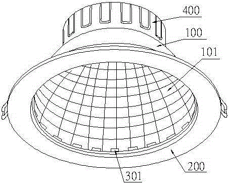
[0012] refer to figure 1 , an embodiment of an LED downlight of the present invention is proposed, which includes a rounded table-shaped lamp housing 100, a face ring 200 connected and fixed on the upper end of the lamp housing 100, fixed on the inner bottom surface of the face ring 200 and facing the lamp housing The LED light source structure illuminated in 100, the drive device box 400 installed at the lower end of the lamp housing 100, and the drive device placed in the drive device box 400 and electrically connected to the LED light source structure.

[0013] The inner surface of the lamp housing 100 is covered with arc-shaped convex surfaces 101 , and the surface of the arc-shaped convex surfaces 101 is coated with a reflective layer capable of reflecting light.

[0014] The LED light source structure includes ...


PUM


Abstract

The invention discloses an LED (light-emitting diode) down lamp which comprises an inverted-truncated-cone-shaped lamp housing, a surface ring, an LED light source structure, a drive unit box and a drive unit, wherein the surface ring is connected and fixed to the upper end of the lamp housing; the LED light source structure is fixedly arranged on the inner bottom surface of the surface ring and irradiates towards the inside of the lamp housing; the drive unit box is installed on the lower end of the lamp housing; the drive unit is arranged in the drive unit box and electrically connected with the LED light source structure; cambered convex surfaces are fully distributed on the internal surface of the lamp housing; the surface of each camber convex surface is coated with a reflective layer capable of reflecting light rays; the LED light source structure comprises an annular substrate fixedly arranged on the inner bottom surface of the surface ring, and a plurality of LED lamp beads which are distributed on the annular substrate and electrically connected with the drive unit; and the LED lamp beads irradiate towards the cambered convex surfaces of the lamp housing, and irradiate towards the outside only under the reflection action of the cambered convex surfaces.

Description

technical field [0001] The invention relates to the technical field of lamps, in particular to an LED downlight. Background technique [0002] The LED light sources of existing LED downlights mostly use point light sources to emit light, and most of them are directed outwards. This design leads to uneven distribution of illumination light intensity, narrow light emitting range, small light emitting surface of LED light source, and excessive light intensity distribution. Concentration causes light spots on the ground, and it is easy to produce glare to make people feel dizzy. In addition, people can directly see the LED lamp beads inside the lamps, which is not beautiful enough. In order to alleviate the above situation, it is generally necessary to install a light-transmitting sheet, which can effectively block the LED lamp beads from being exposed, and can reduce the glare to a certain extent, but this method cannot fundamentally solve the above-mentioned problems . [00...

Claims


Application Information

Patent Timeline
Patent Type & Authority Applications(China)
IPC IPC(8): F21S2/00F21V15/01F21V7/22F21V19/00F21V29/507F21V29/89F21V17/16F21Y101/02
CPCF21S2/00F21V7/22F21V15/01F21V17/16F21V19/0025
Inventor 赵小君
Owner 中山市宝丽兰照明科技有限公司
Why Eureka
Try Eureka