Demountable guide post blanking mould

A blanking die and guide post technology, used in metal processing equipment, forming tools, manufacturing tools, etc., can solve the problems of guide post wear, accuracy reduction, workpiece processing quality decline, etc., to improve service life, ensure strength, reduce The effect of cost of use

Inactive Publication Date: 2016-01-06
CHONGQING YUKUNLONG METALLURGICAL MATERIAL CO LTD
View PDF0 Cites 8 Cited by
  • Summary
  • Abstract
  • Description
  • Claims
  • Application Information

AI Technical Summary

Problems solved by technology

[0003] The blanking die is a common form of blanking die. During the use of the traditional blanking die, in order to ensure a uniform gap between the die and the punch, a guide component composed of a guide post and a guide sleeve is often used to guide the punch. The movement track is used for guidance. During the processing of the workpiece, the guide sleeve will move up and down along the guide post. Therefore, after the mold has been used for a period of time, the guide post will be worn to a certain extent. If the guide post is not replaced in time, the guide post and the guide post will be damaged. The gap between the guide sleeves increases, the guide precision decreases, and the processing quality of the workpiece decreases. Since the guide pillar and the lower mold base in the traditional blanking die adopt an interference fit, when the guide pillar needs to be replaced, the lower mold base must be replaced together, increasing The cost of using the mold

Method used


Image

  • Demountable guide post blanking mould

Examples


Embodiment Construction

[0013] The present invention is described in further detail below by specific embodiments:

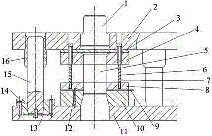
[0014] The reference signs in the drawings include: die handle 1, upper die base 2, backing plate 3, punch fixing plate 4, punch 5, discharge screw 6, discharge spring 7, discharge plate 8, material guide Plate 9 , female die 10 , lower die base 11 , hook stopper pin 12 , washer 13 , bushing 14 , guide post 15 , guide sleeve 16 .

[0015] The example is basically as attached figure 1 As shown, the detachable guide column blanking die includes an upper die part, an elastic pressure discharge part, a lower die part, and a guide part. The upper die part includes a die handle 1, an upper die seat 2, a gasket 3, and a punch fixing plate 4 and the punch 5, the elastic pressure discharge part includes the discharge screw 6, the discharge spring 7 and the discharge plate 8, the lower die part includes the guide plate 9, the female die 10, the lower die base 11 and the hook-shaped stopper pin ...


PUM


Abstract

The invention discloses a demountable guide post blanking mould. The demountable guide post blanking mould comprises an upper mould part and a lower mould part, wherein the upper mould part comprises a mould handle and a convex mould, and an upper mould base is arranged outside the mould handle in a sleeving mode; a convex mould fixing plate is arranged below the upper mould base; the convex mould fixing plate is connected with the convex mould; the lower mould part comprises a lower mould base; a concave mould is arranged on the upper part of the lower mould base; the lower mould part further comprises guide parts, and each guide part comprises a guide post, a guide sleeve and a lining bushing; each guide post is divided into a cylindrical end and a tapered end; the cylindrical end of each guide post is matched with the corresponding guide sleeve; the tapered end of each guide post is matched with the corresponding lining bushing; the guide sleeves can move along the guide posts up and down; the tapered end of each guide post is further provided with a gasket; and each gasket is in threaded connection with the corresponding guide post. The demountable guide post blanking mould has the beneficial effects that the lining bushings are additionally arranged between the guide posts and the lower mould base, the guide posts are detachably connected with the lining bushings, and the lining bushings are detachably connected with the lower mould base, so that detachable connection of the guide posts is realized, and therefore, the problem that the guide posts are required to replace after being worn is effectively solved, and the using cost of the mould is reduced.

Description

technical field [0001] The invention relates to a blanking die structure for blanking, in particular to a detachable guide post blanking die. Background technique [0002] The blanking die is an indispensable process equipment in stamping production, and a good die structure is a reliable guarantee for the realization of the process plan. The quality and precision of stamping parts mainly depend on the quality and precision of the punching die. Whether the structure of the punching die is reasonable and advanced directly affects the production efficiency, the service life of the punching die itself, and the safety and convenience of operation. sex, etc. Due to the different shapes, sizes, precisions, production batches and production conditions of blanking parts, the structure types of blanking dies are also different. [0003] Blanking die is a common form of blanking die. During the use of traditional blanking die, in order to ensure a uniform gap between the die and the...

Claims


Application Information

Patent Timeline
Patent Type & Authority Applications(China)
IPC IPC(8): B21D37/12B21D28/14
Inventor 罗静
Owner CHONGQING YUKUNLONG METALLURGICAL MATERIAL CO LTD
Why Eureka
Try Eureka