Drilling engineering parameter state detecting method

A technology for drilling engineering and state detection, which is applied in the field of oil and gas exploration, and can solve problems such as the failure to realize the diagnosis of abnormal state of drilling engineering parameters on site

Active Publication Date: 2016-01-06
CHINA PETROLEUM & CHEM CORP +1
View PDF4 Cites 7 Cited by
  • Summary
  • Abstract
  • Description
  • Claims
  • Application Information

AI Technical Summary

Benefits of technology

This new technology has several technical benefits that can help make it better than previous technologies for certain applications such as communication systems.

Problems solved by technology

This patented technical problem addressed in this patents relates to improving the accuracy and timeliness with which petrolic well boreers operate while being drilled through various types of rocks such as shale (shake) sands, clay mineral deposits, carbonate sediments, limestone, dolostones, etc., without having direct observation from inside them. Current methods cannot provide accurate results at all times due to factors like environmental conditions and equipment limitations.

Method used


Image

  • Drilling engineering parameter state detecting method
  • Drilling engineering parameter state detecting method
  • Drilling engineering parameter state detecting method

Examples


Embodiment 1

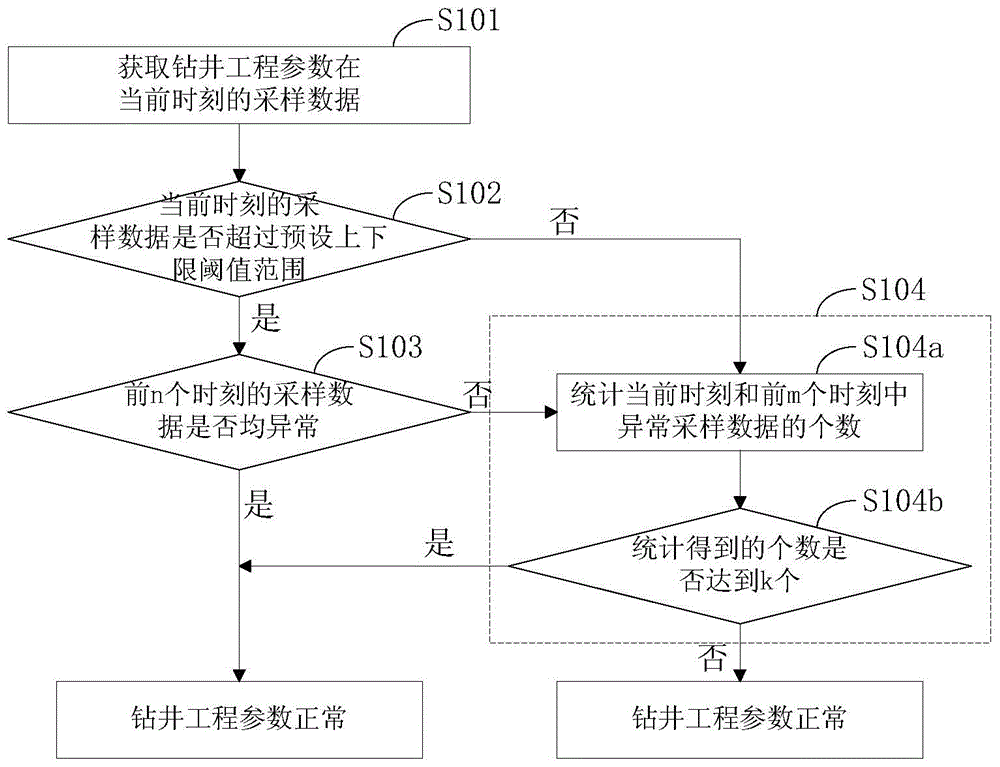
[0049] figure 1 A flow chart of the method for detecting the state of drilling engineering parameters provided by this embodiment is shown.

[0050] Such as figure 1 As shown, in this embodiment, firstly, in step S101, the sampling data of the drilling engineering parameters at the current moment is acquired.

[0051] Because under normal circumstances, the value of the drilling engineering parameter will be within a preset upper and lower threshold range, if it exceeds the upper and lower threshold range, it indicates that the value of the sampling data of the drilling engineering parameter at this time is abnormal. Therefore, in step S102, it is judged whether the sampling data of the drilling engineering parameter at the current moment exceeds the preset upper and lower threshold ranges. If the sampled data at the current moment exceeds the preset upper and lower threshold ranges, it is judged that the sampled data at the current moment is abnormal, and step S103 is execu...

Embodiment 2

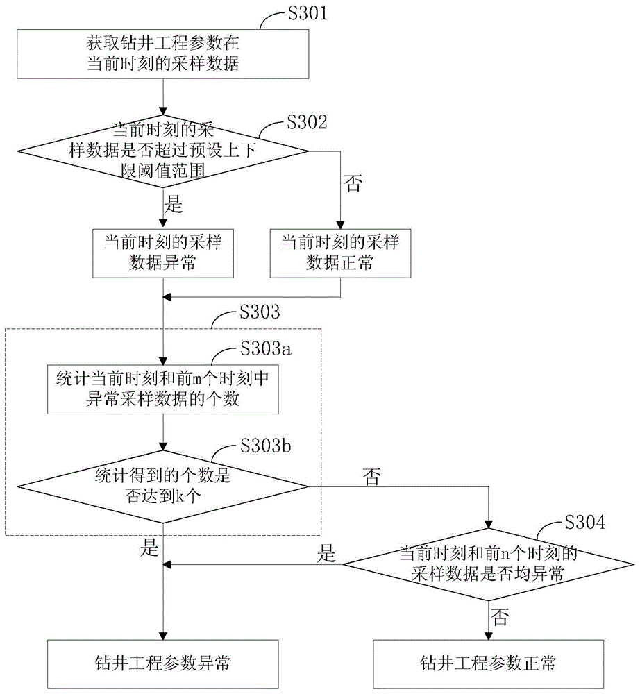
[0067] In the drilling engineering parameter state detection method provided in Embodiment 1, if the number of continuous abnormal sampling moments does not reach n+1, it will be judged whether the number of abnormal data reaches k in the m+1 sampling moments, In this way, the status of drilling engineering parameters can be further judged. However, the drilling engineering parameter monitoring method provided in this embodiment first judges whether the number of abnormal data reaches k in the m+1 sampling time, if not, then continues to judge whether the data at the continuous abnormal sampling time reaches n+ 1, to further judge the status of drilling engineering parameters, image 3 A flow chart of the method for detecting the state of drilling engineering parameters in this embodiment is shown.

[0068] Such as image 3 As shown, first in step S301, the sampling data of the drilling engineering parameters at the current moment is obtained, and in step S302, it is judged ...


PUM


Abstract

The invention discloses a drilling engineering parameter state detecting method. The drilling engineering parameter state detecting method comprises the following steps of (S101) acquiring sampling data of drilling engineering parameters at current time; (S102) judging whether the sampling data at the current time exceeds a preset top and bottom limitation threshold value, determining that the sampling data at the current time are abnormal and carrying out the step (S103) if the sampling data at the current time exceed the preset top and bottom limitation threshold value, and determining that the sampling data at the current time is normal and carrying out the step (S104) if the sampling data at the current time do not exceed the preset top and bottom limitation threshold value; (S103) judging sampling data at preceding n times are abnormal or not, determining that drilling engineering parameters are abnormal if the sampling data at the preceding n times are abnormal, and carrying out the step (S104) if the sampling data at the preceding n times are not abnormal; and (S104) judging the number of abnormal sampling data at the current time and preceding m times reaches k or not, determining that drilling engineering parameters are abnormal if the number of the abnormal sampling data at the current time and the preceding m times reaches k, and determining that the drilling engineering parameters are normal if the number of the abnormal sampling data at the current time and the preceding m times does not reach k. In the above-mentioned steps, m, k and n are positive integers, m is greater than k, and k is greater than n. By the drilling engineering parameter state detecting method, instantaneity and accuracy of judgment results can be guaranteed, and field engineers can be warned for the first time if underground conditions are complicated.

Description


Claims


Application Information

Patent Timeline
Owner CHINA PETROLEUM & CHEM CORP
Why Eureka
Try Eureka