Driving equipment and semiconductor equipment for alternating-current motor

a technology of driving equipment and semiconductor equipment, which is applied in the direction of motor/generator/converter stopper, electric motor speed/torque regulation, dynamo-electric converter control, etc., can solve the problems of motor torque generally tending to ripple, complex and expensive methods, and noise generation

Inactive Publication Date: 2004-03-25
HITACHI LTD
View PDF2 Cites 33 Cited by
  • Summary
  • Abstract
  • Description
  • Claims
  • Application Information

AI Technical Summary

Problems solved by technology

In this 120-degree energizing method, it is known that torque ripples take place at times of switching the windings to be energized (commutation), and thereby noise is generated.
Further, if a motor current waveform includes a large amount of higher harmonic component, motor torque generally tends to have ripples.
This vibration results in noise.
However, this method requires a complicated and expensive apparatus in comparison with the 120-degree energizing method.
In comparison with the 120-degree energizing method, it does not produce an effect large enough to substantially reduce noise when driving a motor.
On the other hand, according to the method disclosed in JP Patent Publication (Unexamined Application) No. 11-341863, the size of the circuit is considered large, and this is not convenient for integrating the circuit into a monolithic IC.
In addition, variations of circuit elements, errors in installation positions of the position detectors, or the like may cause variations in charging and discharging voltage for the capacitor.
However, in such case, an installation error of the Hall IC or the like may also cause the length of the flat part of trapezoidal wave to deviate by approximately .+-.5.degree. from the 60-degree.
However, deviation of .+-.5.degree. may occur due to errors in installing the Hall IC or the like.
This would cause direct-current components to generate in a motor current, thereby causing torque ripples.

Method used


Image

  • Driving equipment and semiconductor equipment for alternating-current motor
  • Driving equipment and semiconductor equipment for alternating-current motor
  • Driving equipment and semiconductor equipment for alternating-current motor

Examples


third embodiment

[0101] the present invention will be described using FIG. 13.

second embodiment

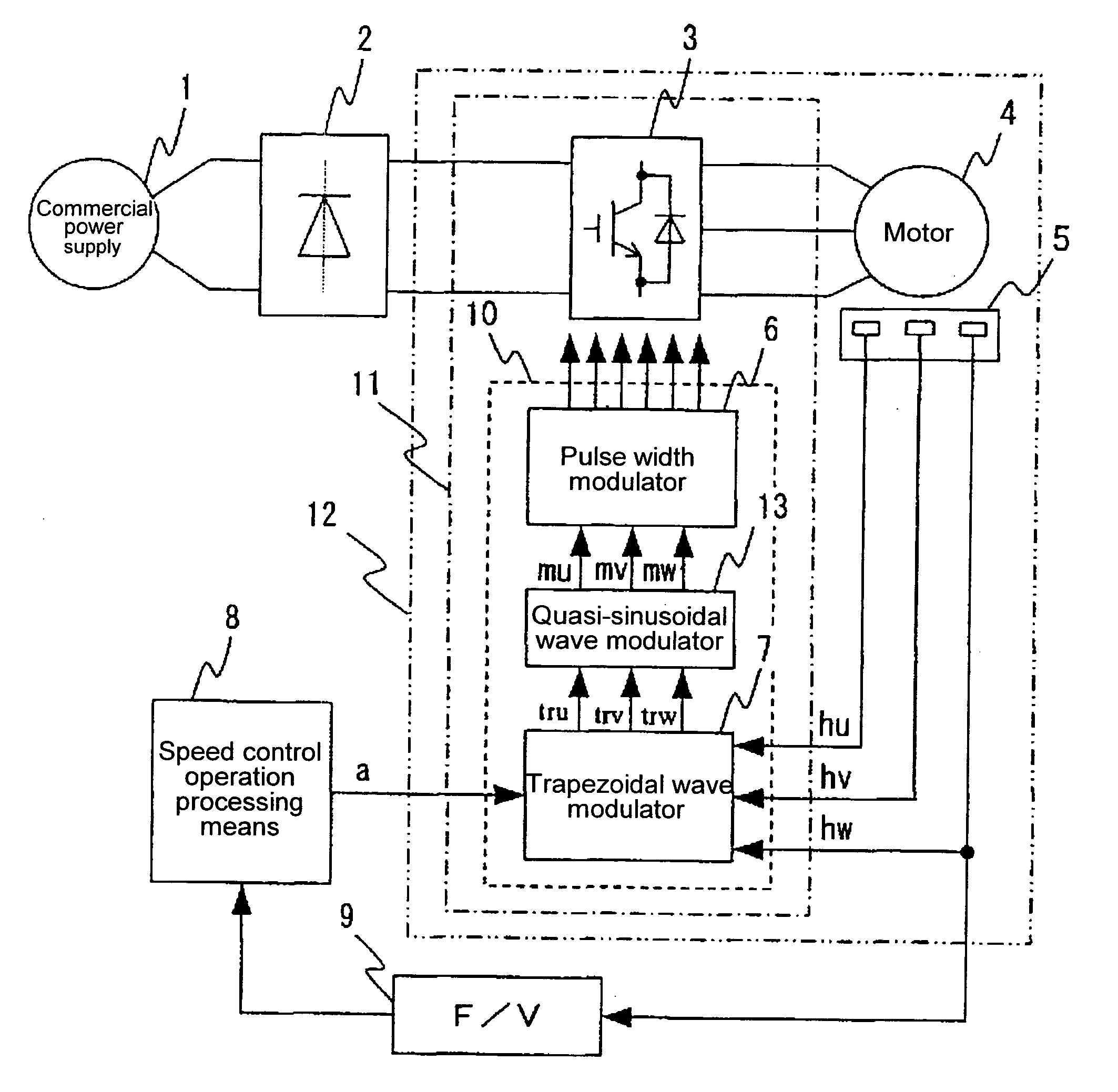
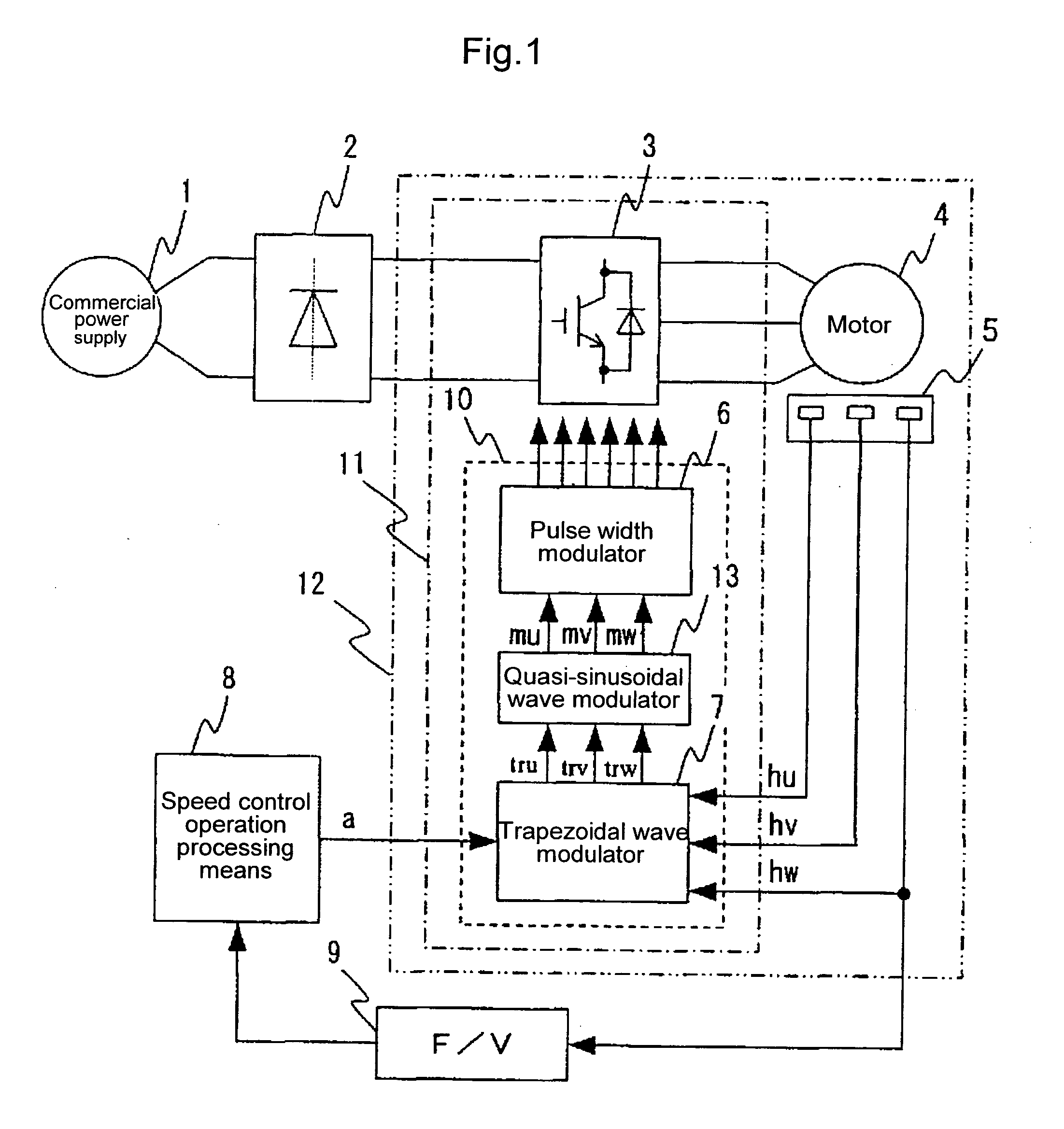
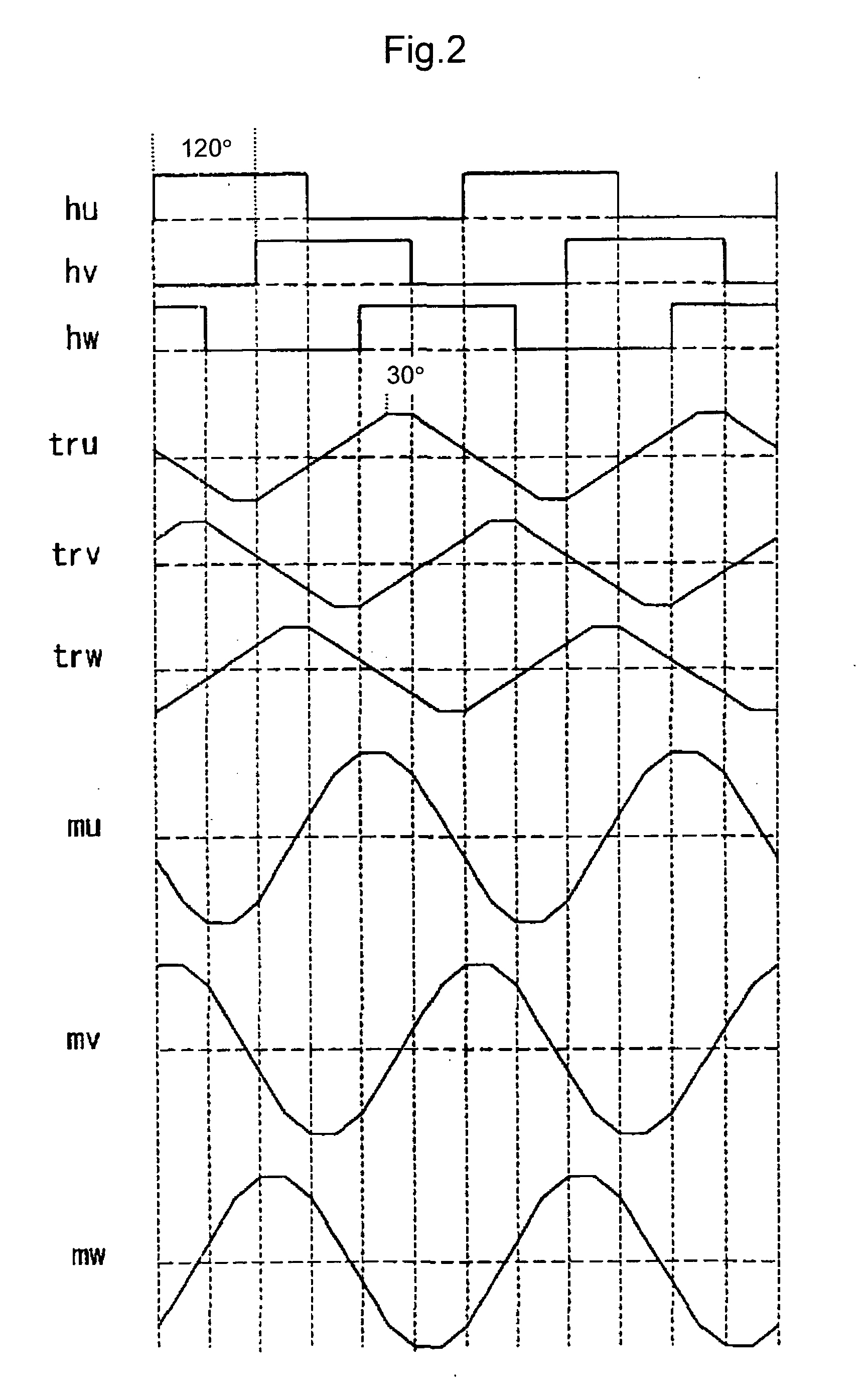
[0102] FIG. 13 shows the configuration of a trapezoidal wave modulator 7A together with its peripheral circuits according to this embodiment. A major difference from the embodiments described above is that the second modulation circuit is removed to reduce the size of the modulation circuit. Due to this, in this embodiment, the trapezoidal wave modulator 7A shown in the above second embodiment is used as it is, and arbitrary trapezoidal wave signals tru, trv, and trw outputted therefrom are directly inputted into a pulse width modulator 6 and are compared with a carrier wave, thereby generating PWM signals.

[0103] In general, a line voltage is applied to the winding of a motor, and thus even when the waveform energized to each phase is trapezoidal, a voltage having a quasi-sinusoidal wave generated by subtraction of trapezoidal waves between two phases is practically applied. When tru, trv, and trw are regarded as three phases of trapezoidal waves, their line voltages are represented...

fourth embodiment

[0120] FIG. 17 shows an operation waveform of the quasi-sinusoidal wave modulator 13B. tru, trv, and trw are trapezoidal waves each having a flat part of 30.degree. for three phases. When Kg2=-1 in the above expressions, 3.phi.=-(tru+trv+trw) becomes, as shown in the figure, a trapezoidal wave having a period 3 times as large as the trapezoidal wave having a flat part of 30.degree.. This is added to tru, trv, and trw thereby to obtain mu1, mv1, and mw1, respectively. Then, they become quasi-sinusoidal waves as shown in FIG. 17, which have a smaller amplitude and a longer flat part than each phase of a trapezoidal wave. These have the same waveform as the quasi-sinusoidal waves obtained in the

[0121] Further, when the values between these phases are taken, quasi-sinusoidal waves represented by mu1-mv1, mv1-mw1, and mw1-mu1 as shown in FIG. 17 are obtained, and they agree with the quasi-sinusoidal waves shown in FIG. 7. In this embodiment, in order to obtain the same quasi-sinusoidal w...


PUM


Abstract

The present invention enables modulated wave signals having extremely small waveform distortion to be generated using a relatively simple circuit, and thereby it is possible to hold down vibrations and noise of a motor, which are attributable to torque ripples. In order to remove defects of the conventional techniques, the circuit generates a plurality of trapezoidal wave signals having at least two constant levels based on position sensing signals of magnetic pole of a motor, generates quasi-sinusoidal wave signals at a quasi-sinusoidal wave modulator based on the plurality of trapezoidal wave signals, and compares the quasi-sinusoidal wave signals with a carrier wave so as to perform PWM control of an inverter.

Description

[0001] 1. Technical Field[0002] The present invention relates to a driving apparatus and a semiconductor apparatus for driving an alternating-current motor of a home electric appliance or an industrial facility.[0003] 2. Background Art[0004] In recent years, in the above-mentioned product field, methods for driving brushless motors by inverters have been expanding. In the field of home electric appliances, the price competition has intensified, and thus there is a demand for inexpensive inverter units. Therefore, for an inverter-driving apparatus with a brushless motor, a 120-degree energizing method which permits a simple circuit configuration and relatively high motor-efficiency is used.[0005] In a motor driving circuit using the 120-degree energizing method, a current is applied to two of three-phase windings for driving the motor by detecting a magnetic-pole position of a motor rotor by a magnetic-pole position detector and controlling the on / off state of each switching element ...

Claims


Application Information

Patent Timeline
Patent Type & Authority Applications(United States)
IPC IPC(8): H02P6/08H02P6/06H02P6/10
CPCH02P6/10H02P2209/07H02P29/0038H02P29/50
Inventor NAKATSUGAWA, JUNNOSUKEOHURA, HITOSHITANAKA, TSUYOSHIENDO, TUNEHIROKAWABATA, YUKIO
Owner HITACHI LTD
Why Eureka
Try Eureka