Torque ripple reduction for a generator

Inactive Publication Date: 2019-03-14
SIEMENS GAMESA RENEWABLE ENERGY AS
View PDF19 Cites 1 Cited by
  • Summary
  • Abstract
  • Description
  • Claims
  • Application Information

AI Technical Summary

Benefits of technology

The present invention is about reducing harmonic torque ripples in a generator system. The invention takes into account the operating region or operating point of the generator system, which improves the reduction of harmonic torque ripples. By injecting a current into the generator system based on one or more reference harmonic currents, the generator system can achieve a desired voltage close to the reference fundamental voltage and reduce torque ripples. The technical effect of this invention is a more efficient and effective reduction of harmonic torque ripples, which improves the performance of the generator system.

Problems solved by technology

Conventionally, torque ripple control may be a big challenge for a high power permanent magnet synchronous machine.
Therefore, conventionally, the torque ripple itself, e.g. higher harmonics of the torque, cannot be used as a feedback in a controller.
However, in this approach, the amplitude and the phase angle of the reference harmonic current may change due to different operating conditions.
Therefore, the fixed parameters are not reliable for the long-term operating torque ripple controller according to the conventional art.
The strain gauge can provide a reliable feedback but the accuracy for the harmonic components may not be good enough.
The microphone measured signal may contain a big delay which the normal controller may not be able to handle.
Conventionally, the torque ripple caused by the permanent magnet on a direct drive wind generator may bring a big vibration and noise.
However, finding an accurate and reliable feedback to represent the IEC position noise has always been a trouble for the closed-loop torque ripple and noise control.
However, the initial amplitude and initial phase may not properly reflect the correct value for the reference harmonic current to be injected to reduce the torque ripple, but other values may be more effective for reducing the harmonic torque ripple.

Method used


Image

  • Torque ripple reduction for a generator
  • Torque ripple reduction for a generator
  • Torque ripple reduction for a generator

Examples


Embodiment Construction

[0059]The illustration in the drawings is in schematic form. It is noted that in different figures, similar or identical elements are provided with the same reference signs or with reference signs, which are different from the corresponding reference signs only within the first digit.

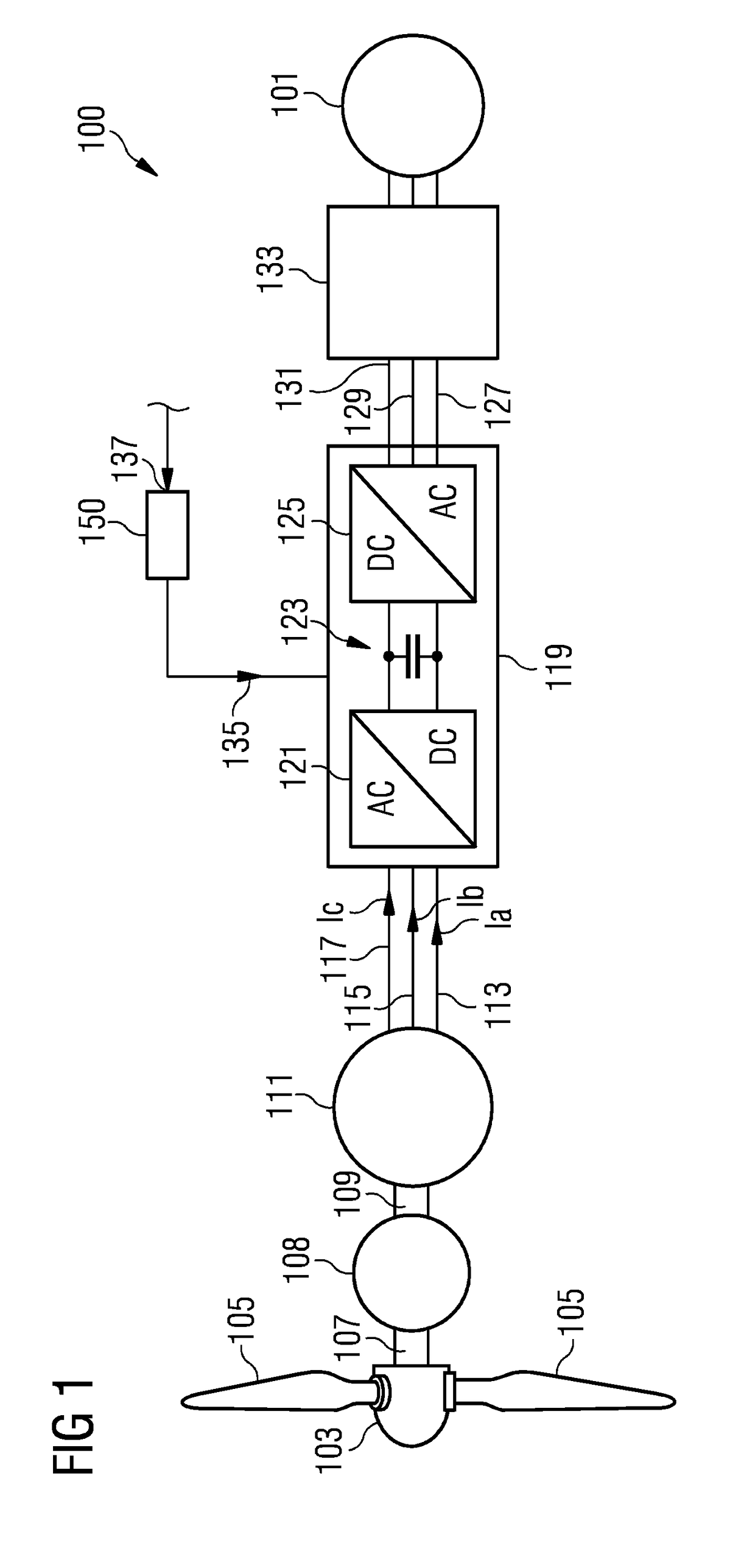
[0060]FIG. 1 illustrates in a schematic form a wind turbine 100 which provides electric energy to a utility grid 101. The wind turbine comprises a hub 103 to which plural rotor blades 105 are connected. The hub is mechanically connected to a main shaft 107 whose rotation is transformed by an optional gear box 108 to a rotation of a secondary shaft 109, wherein the gear box 108 may be optional in which case the wind turbine may be a direct drive wind turbine. The main shaft 107 or the secondary shaft 109 drives a generator 111 which may be in particular a synchronous permanent magnet generator providing a power stream in the three phases or windings 113, 115 and 117 to a converter 119 which comprises a A...


PUM


Abstract

It is provided a method of controlling a generator to reduce a harmonic torque ripple, the method including: measuring a first value of an acceleration using a first accelerometer mounted at a first position of the generator; measuring a second value of an acceleration using a second accelerometer mounted at a second position of the generator; deriving a vibration signal based on a combination of the first value and the second value of the acceleration; deriving, based on the vibration signal, an amplitude and a phase of a reference harmonic current; injecting a current into the generator based on the reference harmonic current.

Description

CROSS-REFERENCE TO RELATED APPLICATIONS[0001]This application claims priority to European application No. EP 17190631.6 having a filing date of Sep. 12, 2017 the entire contents both of which are hereby incorporated by reference.FIELD OF TECHNOLOGY[0002]The following relates to a method and to an arrangement for controlling a generator to reduce a harmonic torque ripple. Further, the following relates to a wind turbine comprising a generator and the arrangement for controlling the generator to reduce a harmonic torque ripple.BACKGROUND[0003]A wind turbine may comprise a rotor shaft with blades connected thereto and may comprise a generator, in particular a high power permanent magnet synchronous machine having a generator rotor which is mechanically connected to the rotor shaft.[0004]Conventionally, torque ripple control may be a big challenge for a high power permanent magnet synchronous machine. The torque of the machine cannot be measured or estimated precisely, which applies in ...

Claims


Application Information

Patent Timeline
IPC IPC(8): H02P21/05H02P21/22F03D9/25
CPCH02P21/05H02P21/22F03D9/25H02P2101/15F05B2220/7068H02P29/50Y02E10/72
Inventor XIE, GE
Owner SIEMENS GAMESA RENEWABLE ENERGY AS
Why Eureka
Try Eureka