[0007] The purpose of the present invention is to solve the aforementioned problems of the aforementioned conventional technology by providing a DC-DC converter that can reduce the
peak value of the current flowing through the
inductance element and that can suppress the
ripple in the output current.
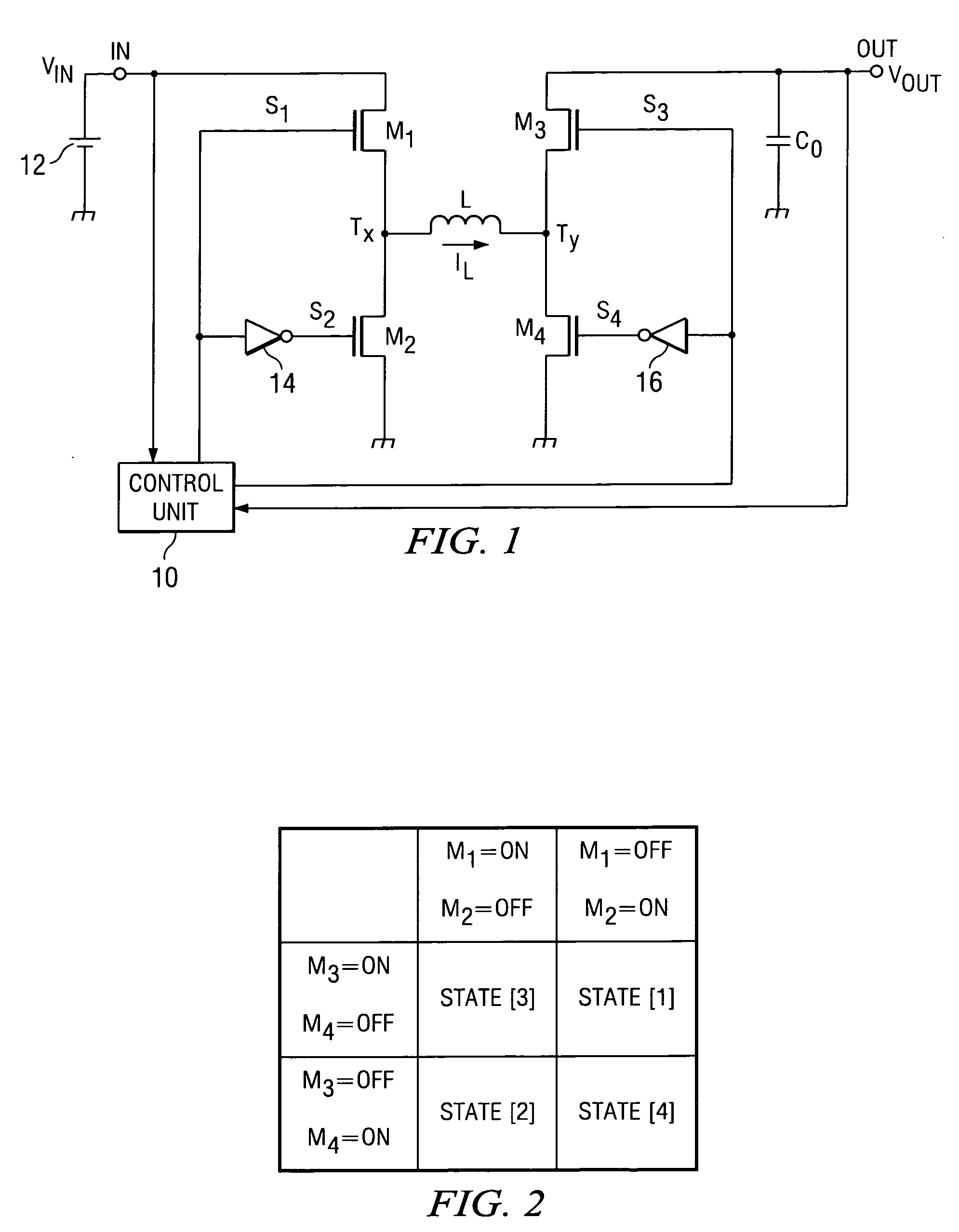
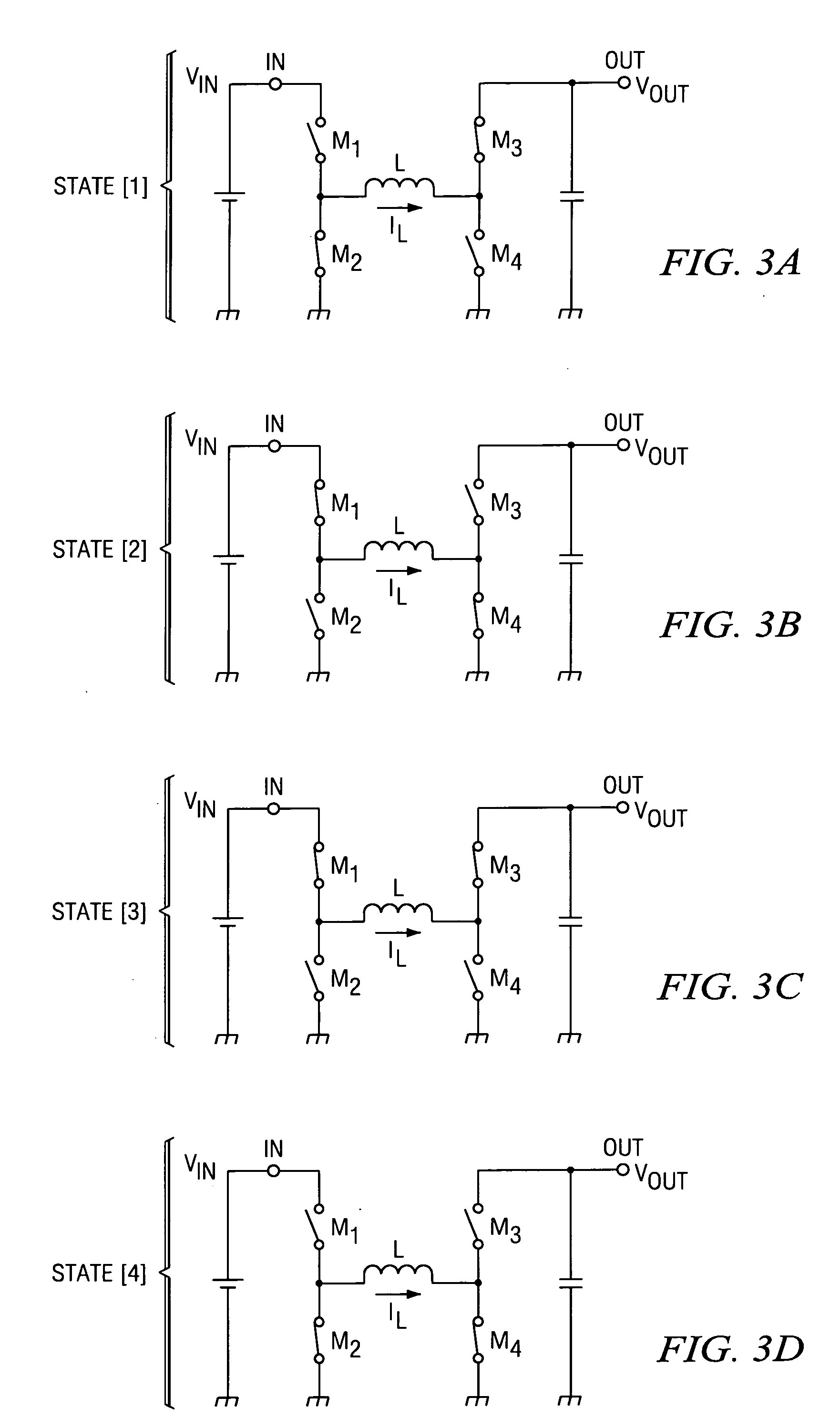
[0009] In the aforementioned configuration, in the first state, one of the terminals of the inductance element is connected to the ground potential via the second switching element in the on state, and the other terminal of the inductance element is connected to the
voltage output terminal via the third switching element in the on state. Energy is released from the inductance element to the voltage output terminal, and the current flowing through the inductance element (coil current) falls at a certain
steep slope or decreases over time. In the second state, one of the terminals of the inductance element is connected to the voltage input terminal via the first switching element in the on state, and the other terminal of the inductance element is connected to the ground potential via the fourth switching element in the on state. Energy from the voltage input terminal is stored in the inductance element, and the coil current rises at a certain
steep slope or increases over time. In the third state, one of the terminals of the inductance element is connected to the voltage input terminal via the first switching element in the on state, and the other terminal of the inductance element is connected to the voltage output terminal via the third switching element in the on state. Energy is released from the inductance element to the voltage output terminal while the energy from the voltage input terminal is stored in the inductance element. The coil current stays at an almost constant level immediately after switching if the input and output voltages are close to each other, and rises or falls at a slope corresponding to the ratio of magnitudes if the input and output voltages are significantly different from each other. In the fourth state, one of the terminals of the inductance element is connected to the ground potential via the second switching element in the one state, while the other terminal of the inductance element is connected to the ground potential via the fourth switching element in the on state. The coil current stays at an almost constant level immediately after the switching, irrespective of the ratio of magnitudes between the input and output voltages. When the aforementioned first, second, third, and fourth states are repeated, in particular, when the fourth state is included in one cycle, the variation or
peak level of the coil current can be reduced. When the
peak level of the coil current is reduced, the
ripple in the output voltage can also be reduced.
[0010] According to a preferable embodiment of the present invention, the four states are repeated in an order such that the fourth state comes after the aforementioned third state with one state, either the first or the second state, inserted between them, and the third state comes after the fourth state with the other state, either the first or the second state, inserted between them. In this case, since the first state, in which the coil current drops sharply, and the second state, in which the coil current rises sharply, are not arranged in succession, in particular, since the fourth state, in which the coil current stays almost unchanged unconditionally, is inserted between the first and second states, the deflection point or the
peak level of the coil current is effectively dulled or suppressed, and the peak level can be further reduced.
[0011] In the present invention, the variation or peak level of the coil current can be reduced if the period of the third and fourth states is longer than the period of the first and second states.
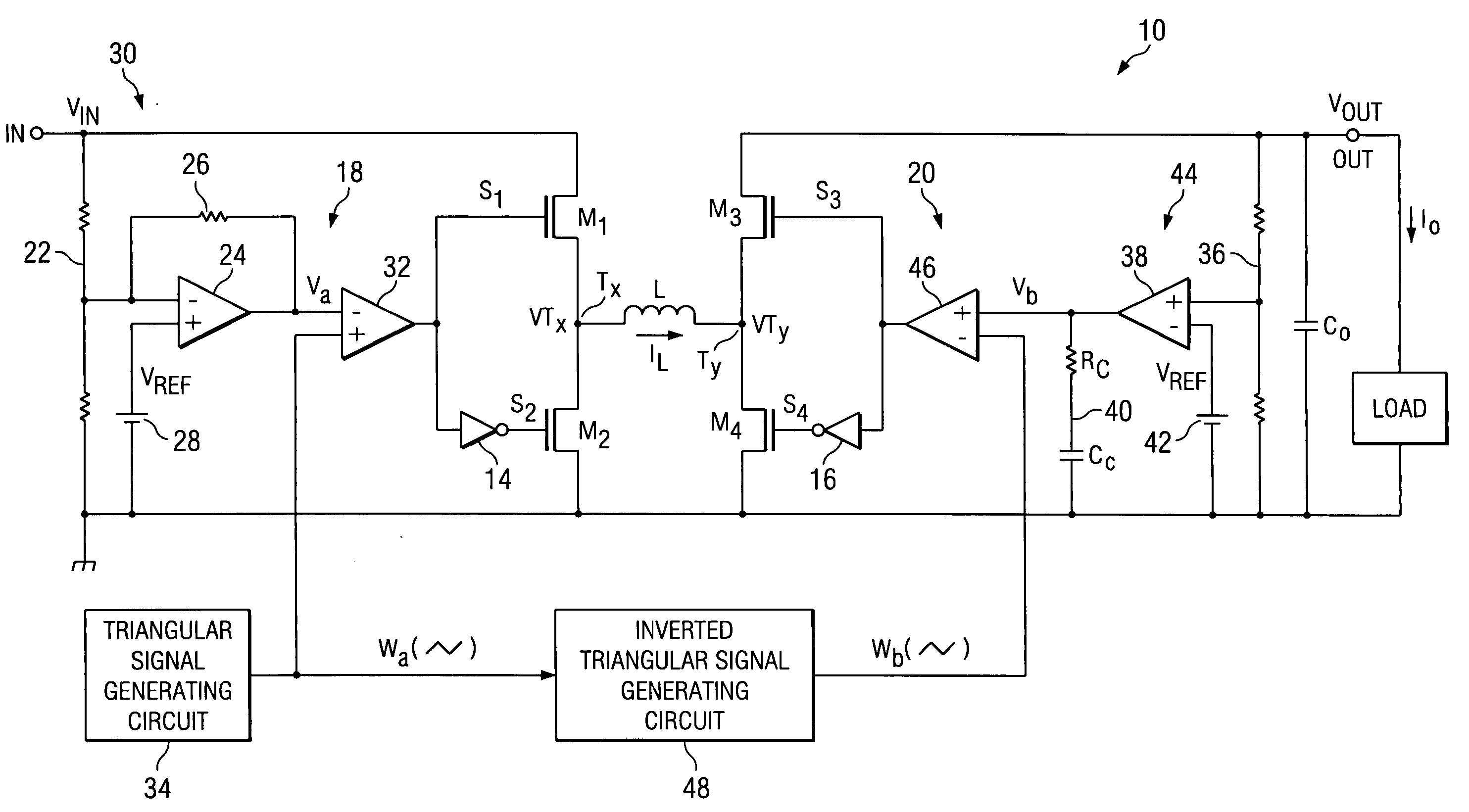
[0018] According to yet another preferred embodiment of the present invention, the maximum peak point and the minimum peak point of the first triangular
signal occur at the same time or close to the maximum peak point and the minimum peak point of the second triangular
signal on the time axis, respectively, and the switching is controlled in the following way. When the voltage level of the aforementioned
feed forward signal is higher than the voltage level of the first triangular signal, the first switching element is off and the second switching element is on. When the voltage level of the aforementioned
feed forward signal is lower than the voltage level of the first triangular signal, the first switching element is on and the second switching element is off. When the voltage level of the aforementioned
feed forward signal is higher than the voltage level of the second triangular signal, the third switching element is off and the fourth switching element is on. When voltage level of the aforementioned feed forward signal is lower than the voltage level of the second triangular signal, the third switching element is on and the fourth switching element is off. In this way, the first, second, third, and fourth states can be repeated in a preferred order.
[0019] According to yet another preferred embodiment of the present invention, the maximum peak point and the minimum peak point of the first triangular signal occur at the same time or close to the maximum peak point and the minimum peak point of the second triangular
signal on the time axis, respectively, and the switching is controlled in the following way. When the voltage level of the aforementioned feed forward signal is higher than the voltage level of the first triangular signal, the first switching element is on and the second switching element is off. When the voltage level of the aforementioned feed forward signal is lower than the voltage level of the first triangular signal, the first switching element is off and the second switching element is on. When the voltage level of the aforementioned feed forward signal is higher than the voltage level of the second triangular signal, the third switching element is on and the fourth switching element is off. When voltage level of the aforementioned feed forward signal is lower than the voltage level of the second triangular signal, the third switching element is off and the fourth switching element is on. In this way, the first, second, third, and fourth states can be repeated in a preferred order.

