A connection device for a target machine and a spliced target machine
A connecting device and target drone technology, which is applied in the field of aviation aircraft, can solve problems such as the inability to meet the quality requirements of the target drone, difficulties in transportation and replacement of disassembled parts, and cumbersome structure of the connecting device, so as to shorten the time required for assembly and use and disassembly and recycling. time, fast replacement, and rapid disassembly
- Summary
- Abstract
- Description
- Claims
- Application Information
AI Technical Summary
Problems solved by technology
Method used
Image
Examples
Embodiment 1
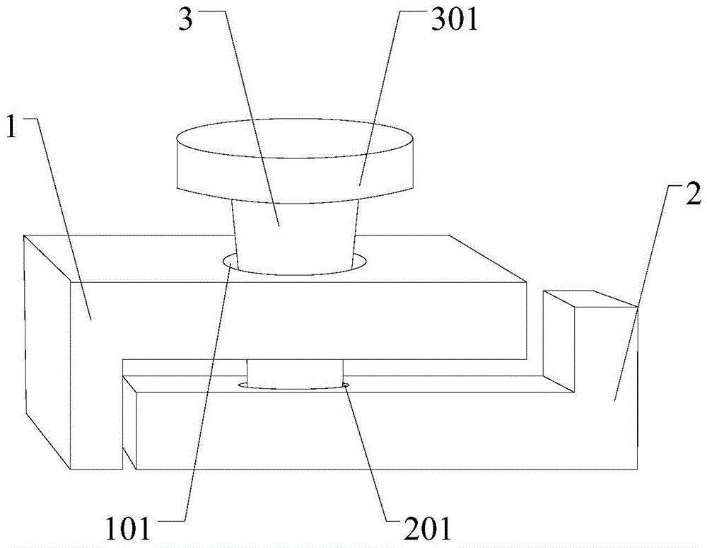
[0039] like figure 1 As shown, Embodiment 1 of the present invention provides a connecting device for a target drone, including a first connecting seat 1 connected to a fuselage 14, a second connecting seat 2 connected to a wing 15, and a connecting device for fixing the first connecting seat 1. The locking pin 3 of the connecting seat 1 and the second connecting seat 2, the first connecting seat 1 and the second connecting seat 2 are fastened up and down, wherein,
[0040]The first connecting seat 1 is provided with a first through hole 101, the second connecting seat 2 is provided with a second through hole 201 communicating with the first through hole 101, and the locking pin 3 is formed from the upper The first through hole 101 and the second through hole 201 are sequentially inserted into the first through hole 101 and the second through hole 201, and the first through hole 101 and the second through hole 201 are adapted to the locking pin 3, and the locking pin 3 The to...
Embodiment 2
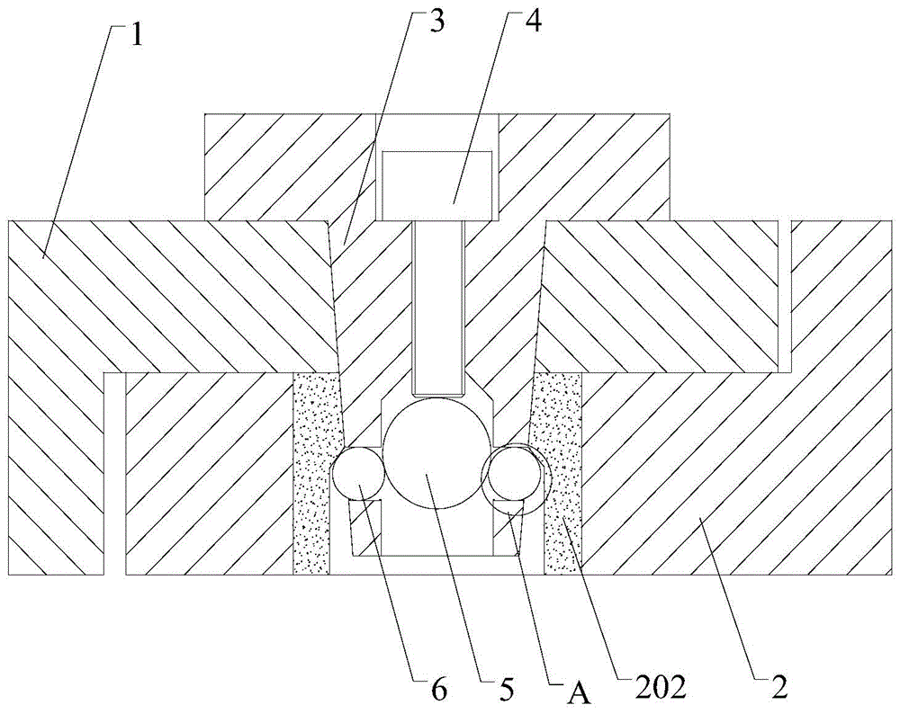
[0044] like Figure 2-5 As shown, Embodiment 2 of the present invention provides a connecting device for a target drone. The difference between this connecting device and Embodiment 1 is that the structure of the locking block and the locking pin 3 is further limited in this technical solution.
[0045] like figure 2 As shown, in order to improve the connection reliability of the connecting device, the technical solution further defines that the locking pin 3 is a truncated cone whose cross-sectional area gradually decreases from top to bottom, and the locking pin 3 of the conical pin structure is It is more firm during the fixing process and can withstand heavier impacts, so that the assembled target machine can adapt to harsher environments. The first through hole 101 is a tapered hole that is adapted to the locking pin 3. The second through hole A bushing 202 adapted to the locking pin 3 is nested in the two through holes 201, and the locking pin 3 is fixedly connected to...
Embodiment 3
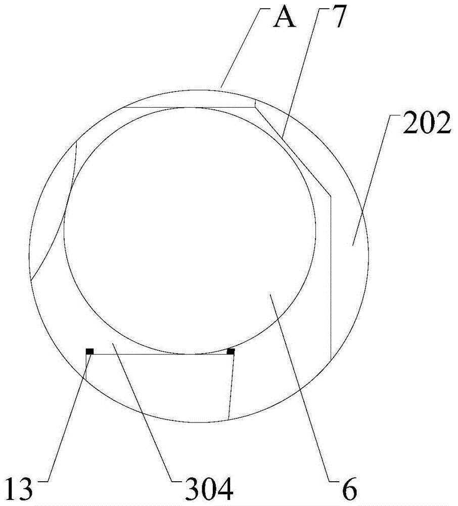
[0056] like Figure 6-9 As shown, Embodiment 3 of the present invention provides a connecting device for a target machine. The difference between this connecting device and Embodiment 2 is that the technical solution further defines that the bushing 202 is connected with a stopper ball 6 Bounce push component.
[0057] like Figure 6-7 As shown, in this technical solution, on the basis of Example 2, the structure of the pushing assembly is further defined, and an installation groove 8 is opened on the bush 202 below the slope 7, and the installation groove 8 There is a push assembly for pushing the limit steel ball 6 to move, the push assembly includes a push rod 9 and a telescopic spring 10 , the end of the push rod 9 is connected to the bottom of the installation groove 8 through the telescopic spring 10 . When the extrusion steel ball 5 forces the three limit steel balls 6 to move outward along the radial direction of the locking pin 3 in the perforation 304, the extrusio...
PUM
 Abstract
Description
Claims
Application Information
 - R&D
- Intellectual Property
- Life Sciences
- Materials
- Tech Scout
- Unparalleled Data Quality
- Higher Quality Content
- 60% Fewer Hallucinations
Browse by: Latest US Patents, China's latest patents, Technical Efficacy Thesaurus, Application Domain, Technology Topic, Popular Technical Reports.
© 2025 PatSnap. All rights reserved.Legal|Privacy policy|Modern Slavery Act Transparency Statement|Sitemap|About US| Contact US: help@patsnap.com


