A heat storage peak-shaving device for a heating system

A heating system and heat storage technology, used in heating systems and central heating, can solve the problems of narrowing the temperature difference between the inlet and return water of the system, unstable return water temperature, high operation and maintenance costs, and eliminate the severe end load. The effect of fluctuation, realization and promotion of behavioral energy saving, low cost of heat transmission and distribution

Active Publication Date: 2019-11-22
NANJING KULANG ELECTRONICS
View PDF4 Cites 0 Cited by
  • Summary
  • Abstract
  • Description
  • Claims
  • Application Information

AI Technical Summary

Problems solved by technology

[0009] However, there are still some problems in the existing system, which are still caused by the fluctuation of the end load of the system:
[0010] 1. The system structure is complex, and the cost of operation and maintenance is high;
[0011] 2. The inertia of the system is relatively large, and the support for "behavioral energy saving" is relatively limited;
[0012] 3. There will be a certain deviation during the operation process, and the temperature difference between the system's inlet and outlet water will decrease, resulting in an increase in system energy consumption
[0015] 1. Traditional constant flow system (L1): Large flow transmission and distribution, the return water temperature of each node is extremely unstable, the temperature difference is small and the flow is large;
[0016] 2. Variable flow system (L2): A well-run variable flow system (smart heating network), the flow change curve is very close to the heat load curve, but the system structure and control are relatively complicated, and the return water temperature of each node will still vary. a certain fluctuation;

Method used


Image

  • A heat storage peak-shaving device for a heating system
  • A heat storage peak-shaving device for a heating system
  • A heat storage peak-shaving device for a heating system

Examples


Embodiment 1

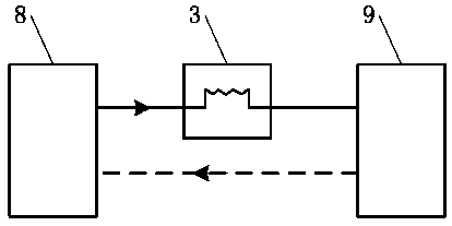
[0062] When the thermal storage peak-regulating device of the present invention is applied to the heat source end (such as a central heating boiler), the primary system mode (such as Figure 5 (Shown), the system includes: a heat source 8, a user end system 9, and the heat storage / heat exchange module 3 is arranged between the heat source 8 and the user end system 9;

[0063] On the water supply end of the heat source 8, one or a group of regulating valves F1 and the water supply section crossover pipe 11 are set, and one or a group of regulating valves F2 and the return water section crossover pipe 12 are set on the return water end of the heat source 8; the connection sequence is :

[0064] Heat source 8→heat source water supply end→regulating valve F1→heat storage / heat exchange module 3 in the water supply section heat exchange pipe 1 / water supply section crossing pipe 11→heating pipe network→user terminal system 9→heating pipe network→regulating valve F2→ The backwater section ...

Embodiment 2

[0074] The existing building heat exchange station cancels the secondary network and uses the primary network to directly connect to the building (see reference 3). The system consists of a plate heat exchanger system and a building variable flow control system, of which the cost of the building variable flow control system is relatively high.

[0075] The two-level system mode of the present invention can be used to replace the building variable flow control system and reduce the cost. The system includes: heat source 8, primary water supply pipe 13, primary return water pipe 14, primary / secondary heat exchanger 15, secondary water supply pipe 16, secondary return water pipe 17, user terminal system 9, heat storage / heat exchange module 3 settings Between the heat source 8 and the end system 9; the primary / secondary heat exchanger 15 is a partition heat exchanger, which can be a plate heat exchanger, a tube heat exchanger or a fin heat exchanger. When the system is running, the ...

Embodiment 3

[0089] The device of the present invention can be directly applied to end users. For example, in a household-divided ring heating system, the device of the present invention is installed at the thermal entrance of the end user. Because the situation of the end user terminal system is more complicated, users should be provided with a flexible system to adapt to different application environments. Such system settings also provide convenience for users' behavioral energy saving.

[0090] Here, the structure of "Mode 2" described in the Summary of the Invention is adopted:

[0091] The heat storage / heat exchange module 3 is divided into at least two modules, namely the first heat exchange module 3a and the second heat exchange module 3b. The first heat exchange module 3a and the second heat exchange module 3b are both equipped with heat storage bodies, The heat storage body adopts a phase change heat storage material, wherein the phase change temperature T of the heat storage body in ...


PUM


Abstract

The invention discloses a heat-storage peak regulating device used for a power supply system, and relates to a heating supply system and method for strengthening the self-adaptive performance of a heat supply system, simplifying a control process and realizing efficient and low-cost operation by utilizing a heat storage means. The device comprises a water supply section heat exchange tube (1), a water return section heat exchange tube (2), a heat storage / heat exchange module (3), a water supply tube of a water supply section heat exchange tube (1) connecting system and a water return tube of a water return section heat exchange tube (2) connecting system; a heat storage body is arranged in the heat storage / heat exchange module (3); the heat storage body is made of a phase-transition heat storage material and has a phase-transition temperature Tx0 which is set to be between the inlet water temperature of the water supply section heat exchange tube (1) and the return water temperature of the water return section heat exchange tube (2). According to the heat-storage peak regulating device, a high-position heat storage and low-position heat release means is adopted to reasonably digest heat exchange temperature difference caused by phase-change heat storage and increase inlet and return water temperature difference during practical operation of the system.

Description

Technical field [0001] The invention relates to a heating system and method that utilizes heat storage means to enhance the self-adaptive performance of the heating system, simplify the control process, and realize efficient and low-cost operation. It belongs to the technical field of heating system design and control. Background technique [0002] With the continuous development of China's heating metering reform, the system structure of the central heating system has undergone great changes. In order to adapt to this structural change, very high requirements are put forward for the system's control ability and automation. [0003] One of the main goals of the heat metering reform is to save energy. Under such a major premise, for the central heating system, it is necessary to achieve two points: heat source "heating on demand" and heat users "heating on demand". [0004] On-demand heating means simply that the heat source supplies heat according to the actual heat demand. At the ...

Claims


Application Information

Patent Timeline
Patent Type & Authority Patents(China)
IPC IPC(8): F24D11/00
Inventor 朱杰
Owner NANJING KULANG ELECTRONICS
Why Eureka
Try Eureka