A twisted optical fiber and its preparation method

A technology for twisting optical fibers and optical fiber preforms, which is applied to cladding optical fibers, polarized optical fibers, light guides, etc., can solve the problems of complicated preparation process, and achieve the effects of improving product quality, simple and reliable preparation method, and reducing production difficulty.

Active Publication Date: 2018-01-12
YANGTZE OPTICAL FIBRE & CABLE CO LTD
View PDF9 Cites 0 Cited by
  • Summary
  • Abstract
  • Description
  • Claims
  • Application Information

AI Technical Summary

Problems solved by technology

However, the preparation process is complicated and requires the preparation of four (or three) stress rods, and the need for vacuuming or the use of ablation and corrosion methods during the spinning and drawing process.

Method used


Image

  • A twisted optical fiber and its preparation method
  • A twisted optical fiber and its preparation method
  • A twisted optical fiber and its preparation method

Examples


preparation example Construction

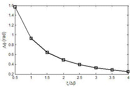
[0031] The method for preparing the rotating optical fiber of the present invention includes two steps: the preparation of the optical fiber preform and the drawing of the optical fiber preform. The optical fiber preform can be prepared by PCVD, MCVD or FCVD. First, deposit the cladding in the liner; then, dope the cladding. The doped area is the annular stress zone. The size and thermal expansion of the annular stress zone The coefficient should satisfy the condition |Δα|×ζ≥0.2. The size of the annular stress zone can be adjusted by changing the deposition process parameters. The thermal expansion coefficient of the annular stress zone can be adjusted by changing the type and amount of dopants. The size and thermal expansion coefficient of the annular stress zone can be adjusted through a limited number of Obtained by routine tests, so I won’t repeat them here.

[0032] Above, Δα is the relative thermal expansion coefficient of the annular stress zone, ζ is the ratio of the cr...

Embodiment 1

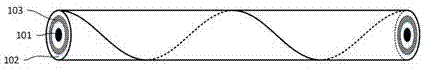
[0035] see figure 2 In this embodiment, the optical fiber includes a core 101, a cladding 102, and a coating layer from the inside to the outside. The cladding 102 includes an annular stress zone 103, and the core 101 and the annular stress zone 103 are not in contact. In this embodiment, the annular stress zone is B 2 O 3 The cladding is doped, and the relative thermal expansion coefficient Δα of the annular stress zone is 300%, and the ratio ζ of its cross-sectional area to the cross-sectional area of ​​the twisted fiber is 20%.

[0036] The preparation process of the rotating optical fiber in this embodiment is:

[0037] Use PCVD method to deposit cladding in the liner tube, doping B in the cladding 2 O 3 A ring-shaped stress zone is formed; then, a cladding layer and a fiber core are sequentially deposited on the inner side of the ring-shaped stress zone, and the rod is shrunk and sintered to obtain an optical fiber preform. The optical fiber preform is rotated, and the optica...

Embodiment 2

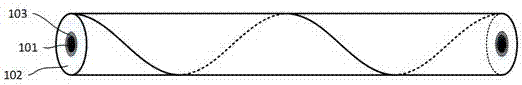
[0039] see figure 2 In this embodiment, the optical fiber includes a core 101, a cladding 102, and a coating layer from the inside to the outside. The cladding 102 includes an annular stress zone 103, and the core 101 and the annular stress zone 103 are not in contact. In this embodiment, the annular stress zone is made of GeO 2 The cladding is doped to obtain a relative thermal expansion coefficient Δα of 200% of the annular stress zone, and the ratio ζ of its cross-sectional area to the cross-sectional area of ​​the rotating fiber is 25%.

[0040] The preparation process of the rotating optical fiber in this embodiment is:

[0041] The cladding layer is deposited in the liner tube by PCVD method, and GeO is doped in the cladding layer 2 A ring-shaped stress zone is formed; then, a cladding layer and a fiber core are sequentially deposited on the inner side of the ring-shaped stress zone, and the rod is shrunk and sintered to obtain an optical fiber preform. Keep the optical fibe...


PUM


Abstract

The invention discloses a twisted optical fiber and a manufacturing method thereof. The twisted optical fiber comprises a fiber core, a cladding layer and a coating layer which are sequentially arranged from inside to outside, wherein the cladding layer contains an annular stress region, and the annular stress region is in contact or not in contact with the fiber core; and the size and thermal expansion coefficient of the annular stress region satisfy the condition that: |Delta alpha|*zeta>=0.2. The manufacturing method of the twisted optical fiber comprises the steps of: step 1, depositing the cladding layer and the fiber core in a lining tube in sequence, contracting and burning to obtain an optical fiber perform, and doping the cladding layer before depositing the fiber core to obtain the annular stress region, which is in contact or not in contact with the fiber core; step 2, and adopting the optical fiber perform for manufacturing the twisted optical fiber. By introducing the annular stress region, the adaptability of the twisted optical fiber to environmental stress is increased, and the manufacturing method thereof is simple and reliable.

Description

Technical field [0001] The invention belongs to the technical field of optical fibers, and specifically relates to a twisted optical fiber and a preparation method thereof. Background technique [0002] Optical fiber is widely used in sensing, such as current transformers, due to its good insulation, natural anti-electromagnetic interference ability, compactness and low loss of optical signal transmission. The usual sensor fiber ring is formed by a low-birefringence fiber around the ring, in which the transmitted polarized light is easily affected by preparation defects (core ellipse, asymmetrical stress, etc.) and external factors (temperature, bending, vibration, etc.). This leads to inaccurate or even wrong test results. At present, the rotating fiber is widely researched and applied. The principle is to introduce circular birefringence through axis rotation on the basis of conventional polarization maintaining fiber (ie linear polarization maintaining fiber), which together ...

Claims


Application Information

Patent Timeline
Patent Type & Authority Patents(China)
IPC IPC(8): G02B6/02G02B6/024
CPCG02B6/02342G02B6/024
Inventor 张心贲曹蓓蓓郑林韦会峰汪洪海童维军
Owner YANGTZE OPTICAL FIBRE & CABLE CO LTD
Why Eureka
Try Eureka