

Twisted optical fiber and manufacturing method thereof
A technology for twisting optical fibers and optical fiber preforms, applied in cladding optical fibers, polarized optical fibers, light guides, etc., can solve the problems of complex preparation process, improve product quality, simple and reliable preparation methods, and improve the accuracy and reliability of test results Effect
- Summary
- Abstract
- Description
- Claims
- Application Information
AI Technical Summary
Problems solved by technology
Method used
Image

Examples
preparation example Construction
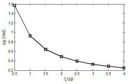
[0031] The preparation method of the spun optical fiber of the present invention comprises two steps: the preparation of the optical fiber preform rod and the drawing of the optical fiber preform rod. The optical fiber preform can be prepared by PCVD method, MCVD method or FCVD method. First, the cladding is deposited in the liner; then, the cladding is doped. The doped area is the annular stress area, and the size and thermal expansion of the annular stress area The coefficient should satisfy the condition |Δα|×ζ≥0.2. The size of the annular stress zone can be adjusted by changing the deposition process parameters, the thermal expansion coefficient of the annular stress zone can be adjusted by changing the type and amount of dopant, and the size and thermal expansion coefficient of the annular stress zone can be adjusted by a limited number of times. Obtained by routine experiments, so I won’t repeat them here.
[0032] Above, Δα is the relative thermal expansion coefficient...
Embodiment 1
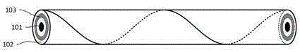
[0035] See figure 2 In this embodiment, the optical fiber in this embodiment consists of a core 101, a cladding 102 and a coating in sequence from the inside to the outside. The cladding 102 contains an annular stress zone 103, and the core 101 and the annular stress zone 103 are not in contact. In this embodiment, the annular stress zone is adopted B 2 o 3 Doping the cladding, the relative thermal expansion coefficient Δα of the obtained annular stress region is 300%, and the ratio ζ of its cross-sectional area to the cross-sectional area of the twisted optical fiber is 20%.
[0036] The preparation process of the spun optical fiber in this embodiment is as follows:
[0037] The cladding is deposited in the liner by PCVD method, and the cladding is doped with B 2 o 3 An annular stress zone is formed; then, a cladding layer and a fiber core are sequentially deposited inside the annular stress zone, and the rod is shrunk and fired to obtain an optical fiber prefabricated...
Embodiment 2
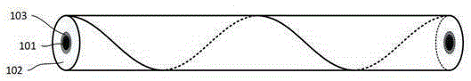
[0039] See figure 2 In this embodiment, the optical fiber in this embodiment consists of a core 101, a cladding 102 and a coating in sequence from the inside to the outside. The cladding 102 contains an annular stress zone 103, and the core 101 and the annular stress zone 103 are not in contact. In this embodiment, the annular stress zone is made of GeO 2 Doping the cladding, the relative thermal expansion coefficient Δα of the obtained annular stress region is 200%, and the ratio ζ of its cross-sectional area to the cross-sectional area of the spun optical fiber is 25%.
[0040] The preparation process of the spun optical fiber in this embodiment is as follows:
[0041] The cladding is deposited in the liner by PCVD method, and the cladding is doped with GeO 2 An annular stress zone is formed; then, a cladding layer and a fiber core are sequentially deposited inside the annular stress zone, and the rod is shrunk and fired to obtain an optical fiber prefabricated rod. Ke...
PUM
 Abstract
Description
Claims
Application Information