Novel stable and automatic drilling device for board side wall

A drilling device, a new type of plate technology, applied in the direction of a fixed drilling machine, etc., can solve the problems of low flexibility, difficulty in ensuring manual work efficiency and work quality, and inability to achieve high-efficiency effects, and achieve convenient use and simple structure. Effect

Inactive Publication Date: 2016-01-20
CHENGDU MALSS IND CO LTD
View PDF9 Cites 4 Cited by
  • Summary
  • Abstract
  • Description
  • Claims
  • Application Information

AI Technical Summary

Problems solved by technology

In the prior art, the equipment for drilling holes in plates is generally not very flexible, and manual filling is required at any time. Often a piece of equipment requires 1-2 workers, which cannot achieve the high efficiency expected by people, especially in When drilling the side wall of the plate, due to the high precision requirements, it is difficult to guarantee the manual work efficiency and work quality

Method used


Image

  • Novel stable and automatic drilling device for board side wall
  • Novel stable and automatic drilling device for board side wall
  • Novel stable and automatic drilling device for board side wall

Examples


Embodiment 1

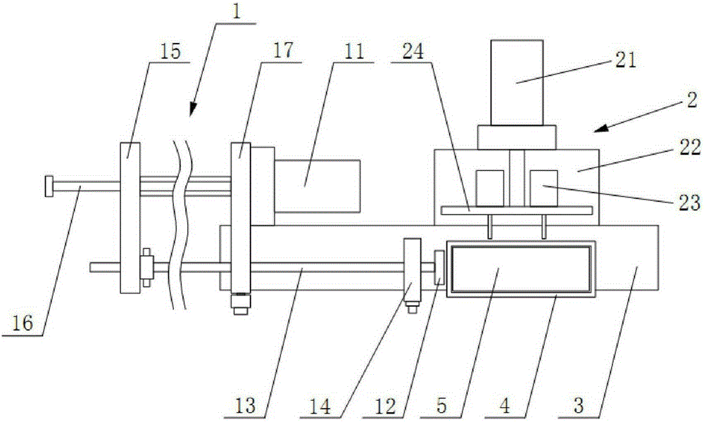
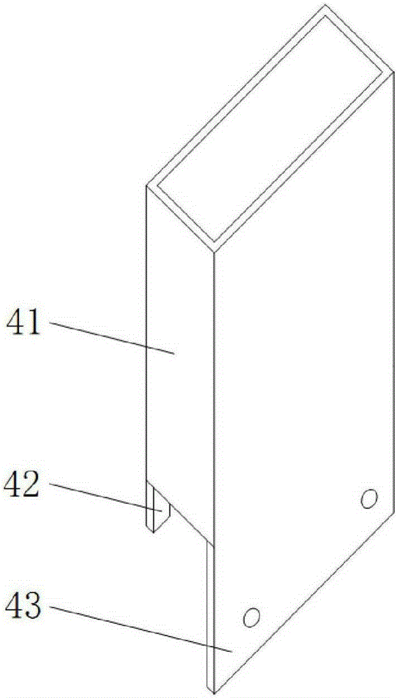
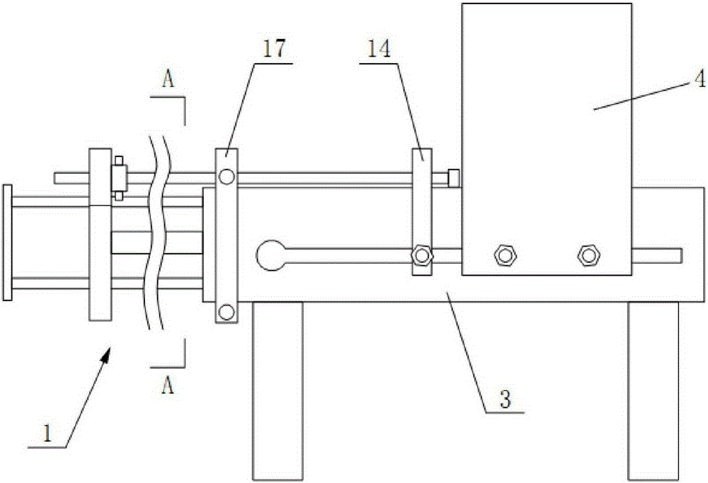
[0021] Such as figure 1 , figure 2 , image 3 and Figure 4 As shown, a new type of stable automatic drilling device for the side wall of a plate, including a workbench 3, a pushing component 1, a drilling component 2 and a raw material bin 4, the raw material bin 4 is set above the workbench 3, and the pushing component 1 is set in the raw material bin 4 On the workbench 3 outside one end, the drilling assembly 2 is arranged on the workbench 3 outside the side of the raw material to be drilled. The push assembly 1 includes a pneumatic cylinder 11, a connecting plate 15, a guide plate 14, a push rod 13 and a pushing plate 12. The pneumatic cylinder 11 is arranged on the workbench 3, and one end of the piston rod of the pneumatic cylinder 11 is fixed to the connecting plate 15. Connection, one end of the push rod 13 is connected with the connecting plate 15, the other end passes through the guide plate 14 and connected with the push plate 12, the push plate 12 is located at...

Embodiment 2

[0023] Such as figure 1 , figure 2 , image 3 and Figure 4 As shown, a new type of stable automatic drilling device for the side wall of a plate, including a workbench 3, a pushing component 1, a drilling component 2 and a raw material bin 4, the raw material bin 4 is set above the workbench 3, and the pushing component 1 is set in the raw material bin 4 On the workbench 3 outside one end, the drilling assembly 2 is arranged on the workbench 3 outside the side of the raw material to be drilled. The push assembly 1 includes a pneumatic cylinder 11, a connecting plate 15, a guide plate 14, a push rod 13 and a pushing plate 12. The pneumatic cylinder 11 is arranged on the workbench 3, and one end of the piston rod of the pneumatic cylinder 11 is fixed to the connecting plate 15. Connection, one end of the push rod 13 is connected with the connecting plate 15, the other end passes through the guide plate 14 and connected with the push plate 12, the push plate 12 is located at...


PUM


Abstract

The invention discloses a novel stable and automatic drilling device for a board side wall. The novel stable and automatic drilling device comprises a workbench, a pushing assembly, a drilling assembly and a raw material bin. The raw material bin is arranged above the workbench. The pushing assembly is arranged at the portion, outside one end of the raw material bin, of the workbench. The drilling assembly is arranged at the portion, outside the side to be drilled of a raw material, of the workbench. The pushing assembly comprises a first pneumatic cylinder, a connecting board, a guide board, a push rod and a first push board. The first pneumatic cylinder is arranged on the workbench. One end of a piston rod of the first pneumatic cylinder is fixedly connected with the connecting board. One end of the push rod is connected with the connecting board, and the other end of the push rod penetrates the guide board to be connected with the first push board. The first push board is located at one end of the raw material bin. The height of the first push board is smaller than the thickness of a raw material board. The connecting board is provided with a through pipe. The push rod is in slide fit with the through pipe. The pipe wall of the through pipe is provided with a clamping screw. The drilling assembly comprises a work board, a second pneumatic cylinder, a second push board and electric drills.

Description

technical field [0001] The invention belongs to the field of furniture processing equipment, and in particular relates to a novel plate side wall stable automatic drilling device. Background technique [0002] In the process of furniture processing, it is necessary to drill holes in the furniture panels to meet the splicing needs of each part of the furniture. In the prior art, the equipment for drilling holes in plates is generally not very flexible, and manual filling is required at any time. Often a piece of equipment requires 1-2 workers, which cannot achieve the high efficiency expected by people, especially in When drilling the side wall of the plate, due to the high precision requirements, it is difficult to guarantee the manual work efficiency and work quality. Therefore, there is an urgent need for research and development of special equipment for drilling sidewalls of plates. Contents of the invention [0003] The purpose of the present invention is to provide ...

Claims


Application Information

Patent Timeline
Patent Type & Authority Applications(China)
IPC IPC(8): B27C3/02
Inventor 钟锐
Owner CHENGDU MALSS IND CO LTD
Why Eureka
Try Eureka