Hydraulic oil pipe inner cutter

A hydraulic and tubing technology, applied in the direction of wellbore/well components, earthwork drilling and production, etc., can solve the problems of inaccurate cutting position, high failure rate of equipment, difficult to realize cutting, etc., and achieve convenient and accurate pressure adjustment, accurate and rapid cutting , easy cutting effect

Active Publication Date: 2018-07-10
YANCHENG DONGRONG PETROLEUM MACHINERY CO LTD
View PDF6 Cites 0 Cited by
  • Summary
  • Abstract
  • Description
  • Claims
  • Application Information

AI Technical Summary

Problems solved by technology

At present, most of the oil pipe cutting instruments used are thermal cutting, and combustible gas will be used in the cutting process, which is prone to the danger of explosion, and the cutting position is not accurate, and some are difficult to achieve cutting
It needs to use cold cutting equipment for operation. At present, there is no mature cold cutting product suitable for use in the well site, which is manifested in the disadvantages of high equipment failure rate, complex structure, and poor cutting effect.

Method used


Image

  • Hydraulic oil pipe inner cutter
  • Hydraulic oil pipe inner cutter
  • Hydraulic oil pipe inner cutter

Examples


Embodiment Construction

[0015] The specific content of the present invention will be described in detail below in conjunction with the accompanying drawings and specific embodiments.

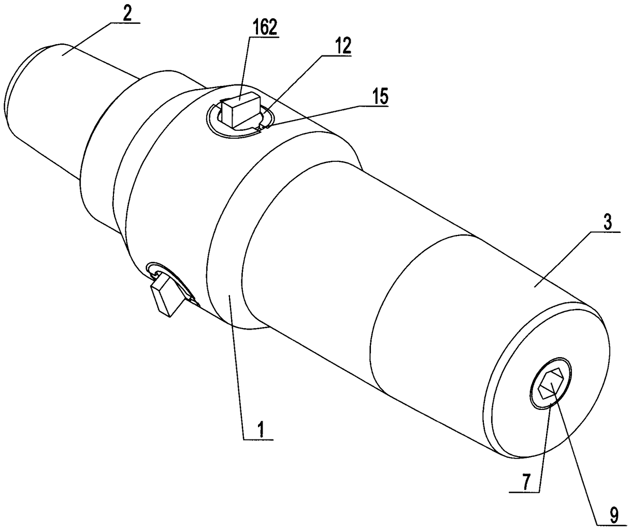
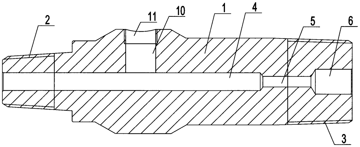
[0016] Such as figure 1 , figure 2 , image 3 , Figure 4 , Figure 5 , Image 6 , Figure 7 As shown, the hydraulic oil pipe inner cutter includes: an oil pipe inner cutter cutter body 1, an upper connection end 2 is arranged at one end of the oil pipe inner cutter cutter body 1, and an upper connection end 2 is arranged at one end of the oil pipe inner cutter cutter body 1; The other end of the body 1 is provided with a lower connection end 3, and a water inlet passage 4, a pressurization passage 5, and a pressure adjustment screw installation cavity 6 are arranged in the oil pipe cutter body 1, and the pressure adjustment screw is installed The cavity 6 is internally threaded with a pressure adjusting screw 7 that cooperates with it. A pressure adjusting channel 8 is provided in the pressure adjusting screw 7...


PUM


Abstract

The invention discloses a hydraulic oil pipe inner cutting knife which comprises a cutting knife body, wherein an upper connecting end is arranged at one end of the cutting knife body; a lower connecting end is arranged at the other end of the cutting knife body; a water inlet passage, a pressurizing passage and a pressure adjustment screw mounting cavity are arranged in the cutting knife body; a pressure adjustment screw mutually matched with the pressure adjustment screw mounting cavity is in threaded connection with the pressure adjustment screw mounting cavity; a pressure adjustment passage is arranged in the pressure adjustment screw; a pressure adjustment screw fastening groove communicated with the pressure adjustment passage is formed in the lower end of the pressure adjustment screw; a plurality of cutting knife mounting cavities and guide sleeve mounting cavities communicated with the water inlet passage are arranged in the cutting knife body; guide sleeves mutually matched with the guide sleeve mounting cavities are in threaded connection with the guide sleeve mounting cavities; mounting cavities and limiting convex edges are arranged in the guide sleeves; guide sleeve fastening grooves are formed in the outer sides of the guide sleeves; cutting knives and compression springs are arranged in the cutting knife mounting cavities.

Description

technical field [0001] The invention relates to a workover equipment in the petroleum industry, in particular to a hydraulic oil pipe internal cutter. Background technique [0002] In the process of oilfield development, due to formation factors, improper measures, aging of wellhead devices, etc., blowouts out of control often occur, and the tubing must be cut off before workover. At present, most of the oil pipe cutting instruments used are thermal cutting, and combustible gas is used in the cutting process, which is prone to the danger of explosion, and the cutting position is not accurate, and some of them are difficult to achieve cutting. It is necessary to use cold cutting equipment for operation. At present, there is no mature cold cutting product suitable for use in the well site, which has the disadvantages of high failure rate, complex structure, and poor cutting effect. Contents of the invention [0003] The problem to be solved by the present invention is to pr...

Claims


Application Information

Patent Timeline
Patent Type & Authority Patents(China)
IPC IPC(8): E21B29/00
Inventor 王玉刚
Owner YANCHENG DONGRONG PETROLEUM MACHINERY CO LTD
Why Eureka
Try Eureka