Air conditioner system and control method thereof

A technology of an air conditioning system and a control method, which is applied in heating and ventilation control systems, heating and ventilation safety systems, heating methods, etc., can solve the problems of strong wind, excessive compressor frequency that cannot be adjusted, and loud noise, etc. Shortened time and reasonable air output

Inactive Publication Date: 2016-01-20
GREE ELECTRIC APPLIANCES INC
View PDF8 Cites 6 Cited by
  • Summary
  • Abstract
  • Description
  • Claims
  • Application Information

AI Technical Summary

Problems solved by technology

[0002] At present, conventional household air conditioning system components mainly include a compressor, a four-way reversing valve, an outdoor unit heat exchanger, a throttling device, and an indoor unit heat exchanger. The heating module, due to the difference between the cooling and heating systems, makes it difficult to achieve the best operation and use of the system; the form of the indoor unit mainly includes wall-mounted units, land-mounted units, cabinet units, etc., installed on the wall or standing indoors , although the air outlet angle and direction can be adjusted through the position of the air deflector, the air outlet position is fixed due to the installation position of the indoor unit; due to the limitation of the installation position and the air outlet position, it is difficult for the air conditioner to achieve true meaning during operation. The air is blown from the top of the cooling and the wind is blown from the bottom of the heating, so that there are obvious temperature gradients in the room, a strong sense of blowing, and relatively loud noise; in terms of adjusting the cooling and heating capabilities, the traditional inverter air conditioner mainly operates by adjusting the compressor. Frequency to adapt to different working conditions, but limited by the local performance of the compressor, the frequency of the compressor cannot be adjusted too high or too low, which makes the range of cooling and heating capacity output by the compressor relatively limited

Method used


Image

  • Air conditioner system and control method thereof
  • Air conditioner system and control method thereof
  • Air conditioner system and control method thereof

Examples


Embodiment Construction

[0031] The present invention is described below based on examples, but the present invention is not limited to these examples. In the following detailed description of the invention, some specific details are set forth in detail. The present invention can be fully understood by those skilled in the art without the description of these detailed parts. To avoid obscuring the essence of the present invention, well-known methods, procedures, procedures, and components have not been described in detail.

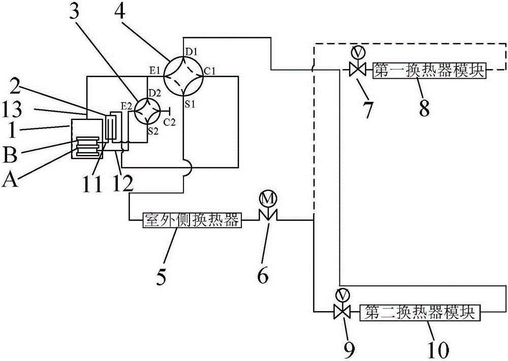
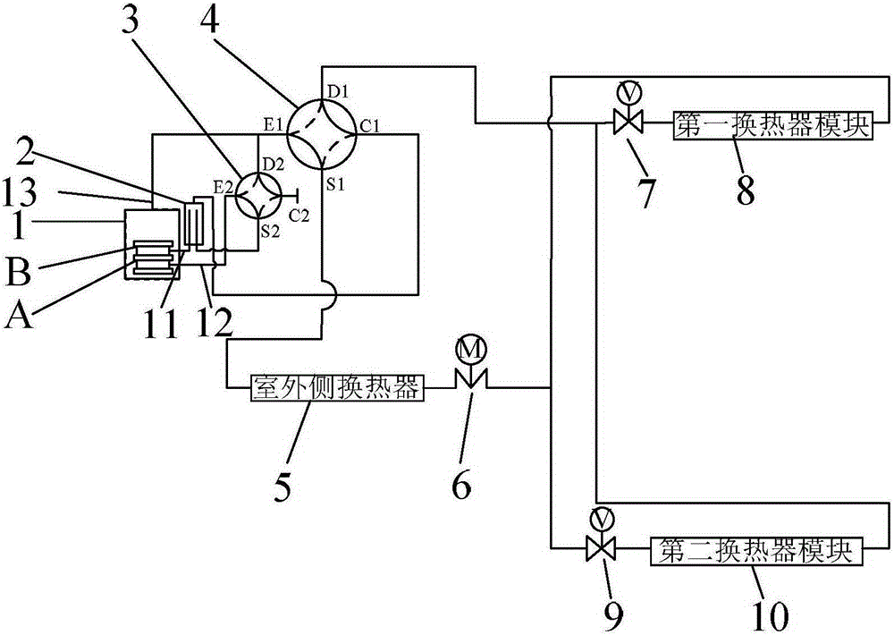
[0032] Below to Figure 1-4 As shown, the composition structure and working method of the air conditioning system of the present application will be further described. The air conditioning system of the present application includes a compressor 1, a first four-way valve 4, an indoor heat exchanger assembly, a throttling assembly 6, and an outdoor heat exchanger assembly 5 connected into a loop; the indoor heat exchanger assembly includes a parallel first heat exchanger Heater m...


PUM


Abstract

The invention provides an air conditioner system used for achieving upward air-out of refrigerating and downward air-out of heating. The air conditioner system comprises a compressor, a first four-way valve, an indoor heat exchanger assembly, a throttling assembly and an outdoor heat exchanger assembly which are connected into a loop. The indoor heat exchanger assembly comprises a first heat exchanger module and a second heat exchanger module which are connected in parallel. The installation position of the first heat exchanger module on the air conditioner system is higher than that of the second indoor heat exchanger module. The working modes of the air conditioner system comprise the first refrigerating mode that only the first heat exchanger module works, the first heating mode that only the second heat exchanger module works and/or the second refrigerating mode and the second heating mode that the two heat exchanger modules work simultaneously. The invention further provides a control method of the air conditioner system. Independent work and simultaneous work of the two heat exchanger modules can be achieved.

Description

technical field [0001] The invention relates to the field of air conditioning, in particular to an air conditioning system and a control method thereof. Background technique [0002] At present, the conventional household air conditioning system components mainly include compressors, four-way reversing valves, outdoor unit heat exchangers, throttling devices, and indoor unit heat exchangers. The heating module, due to the difference between the refrigeration and heating systems, makes it difficult to achieve the best operation and use of the system; the form of the indoor unit mainly includes wall-mounted units, land-mounted units, cabinet units, etc., installed on the wall or standing indoors , although the air outlet angle and direction can be adjusted through the position of the air deflector, the air outlet position is fixed due to the installation position of the indoor unit; due to the limitation of the installation position and the air outlet position, it is difficult...

Claims


Application Information

Patent Timeline
Patent Type & Authority Applications(China)
IPC IPC(8): F24F11/00
Inventor 张辉廖敏熊军吴俊鸿罗永前连彩云彭光前田雅颂
Owner GREE ELECTRIC APPLIANCES INC
Why Eureka
Try Eureka