Bi-rotation electric generator

A generator and outer rotor technology, applied in synchronous generators and other directions, can solve the problems of large capacity and small volume, and achieve the effect of large capacity, small volume and convenient maintenance.

Inactive Publication Date: 2002-07-03
崔勤川
View PDF0 Cites 1 Cited by
  • Summary
  • Abstract
  • Description
  • Claims
  • Application Information

AI Technical Summary

Problems solved by technology

[0002] At present, there are all kinds of generators, but there is no rotor with no winding, no slip ring, no carbon brush, no permanent magnet material, small size, large capacity, and can work normally in a relatively harsh environment. , and a generator with a relatively long service life

Method used


Image

  • Bi-rotation electric generator
  • Bi-rotation electric generator
  • Bi-rotation electric generator

Examples


Embodiment Construction

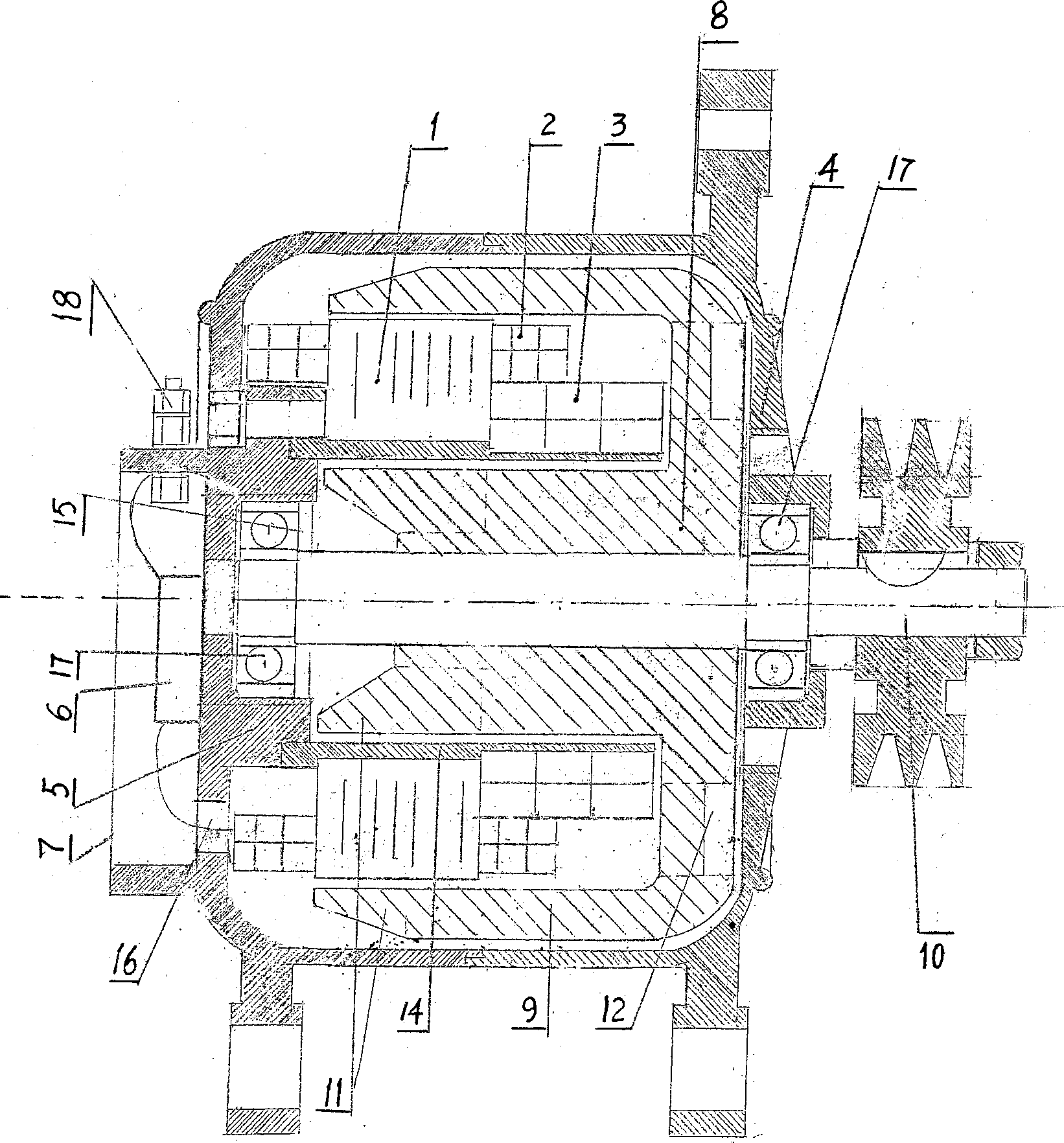
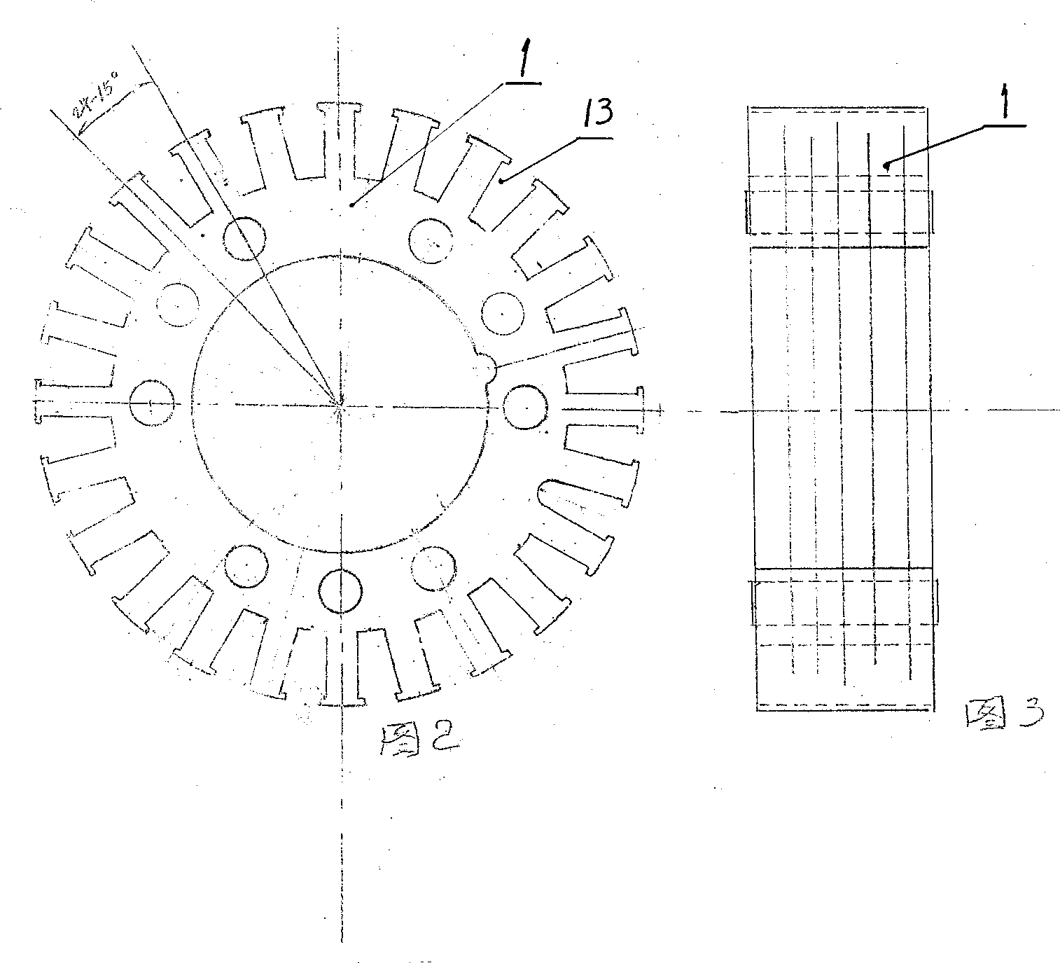
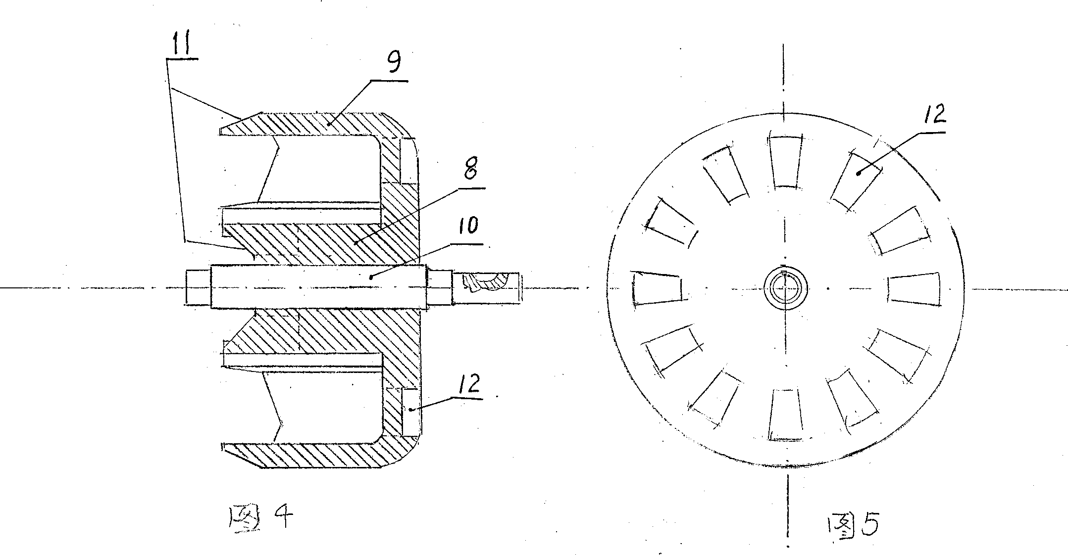
[0025] Such as Picture 1-1 As shown in 5, the generator is composed of inner and outer rotors, stator core 1, stator winding 2, field winding 3, front end cover 4, rear end cover 5, rectifier block 6 and shield 7 thereof. The inner rotor 8 is cylindrical, and the outer rotor 9 is barrel-shaped. The left end of the inner rotor 8 is connected with the inner bottom of the outer rotor 9 such as a barrel to form an inner and outer rotor. The inner and outer rotors are concentric, and the center of the inner and outer rotors There are circular through holes, which pass through the generator shaft 10; the left ends of the inner and outer rotors have 6 magnetically conductive teeth 11, and there are 12 other teeth on the outer rotor 9 barrel-shaped bottom except for the 10 holes in the center that pass through the generator shaft. Trapezoidal ventilation holes 12. The stator core 1 is made of folded and riveted silicon steel sheets. The shape of the stator core 1 is cylindrical. The...


PUM


Abstract

A dual-rotator electric generator is composed of internal and external rotors, stator, exciting windings, front and back end covers, rectifying block and protection hood, and features that said rotor does not have winding, slide ring, carbon brush and permanent-magnet material. Its advantages include small size, light weight, high capacity and long service life.

Description

1. Technical field [0001] The invention relates to a generator, in particular to a double-spin generator with inner and outer rotors. 2. Technical background [0002] At present, there are all kinds of generators, but there is no rotor with no winding, no slip ring, no carbon brush, no permanent magnet material, small size, large capacity, and can work normally in a relatively harsh environment. , and a generator with a relatively long service life. 3. Contents of the invention [0003] The purpose of the present invention is to design a double-rotary generator, which has inner and outer rotors, and the inner and outer rotors rotate around the stator core, stator windings, and field windings; the generator rotor has no windings and no slip rings , No carbon brush, no permanent magnet material, so small size, light weight, large capacity, easy maintenance. The service life is relatively long, which is used to make up for the shortage of existing generators. [0004] The ...

Claims


Application Information

Patent Timeline
Patent Type & Authority Applications(China)
IPC IPC(8): H02K19/16
Inventor 董玉良崔勤川温志国
Owner 崔勤川
Why Eureka
Try Eureka