Tubular pile concrete placing device

A technology for concrete and concrete conveying pipes, applied in the direction of supply devices, manufacturing tools, etc., can solve problems such as difficult cleaning, falling on the cloth flat car 3 or the construction site, and dirty construction sites

Inactive Publication Date: 2016-01-27
ZOOMLION HEAVY IND CO LTD
View PDF8 Cites 3 Cited by
  • Summary
  • Abstract
  • Description
  • Claims
  • Application Information

AI Technical Summary

Problems solved by technology

When the pipe pile form 2 is far away from the concrete delivery pipe 1, the concrete attached to the outer pipe wall will fall on the distribution flat car 3 or the construction site, making the construction site dirty and difficult to clean, and also causing a waste of part of the concrete

Method used


Image

  • Tubular pile concrete placing device
  • Tubular pile concrete placing device
  • Tubular pile concrete placing device

Examples


Embodiment Construction

[0027] Specific embodiments of the present invention will be described in detail below in conjunction with the accompanying drawings. It should be understood that the specific embodiments described here are only used to illustrate and explain the present invention, and are not intended to limit the present invention.

[0028] In the invention, where there is no indication to the contrary, the use of orientation words such as "up, down, top, bottom" usually refers to the direction shown in the drawings or refers to the vertical, perpendicular or gravitational direction. Words are used to describe the mutual positional relationship of each component. In addition, unless otherwise stated, "left and right" generally refer to the left and right directions in the horizontal direction of the paper.

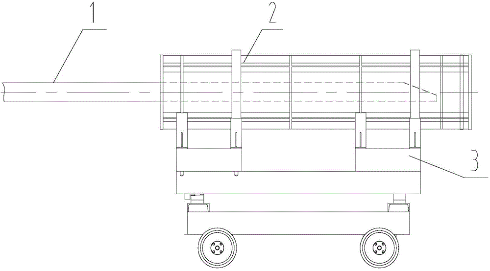
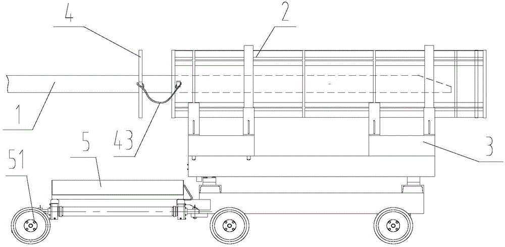
[0029] Such as figure 2 As shown, the present invention provides a pipe pile concrete distribution equipment, the pipe pile concrete distribution equipment includes a concrete deliver...


PUM


Abstract

The present invention discloses a tubular pile concrete placing device. The device comprises a concrete conveying pipe (1), a tubular pile die (2), a placement flat wagon (3) and an outer tube wall sleeving member (4), wherein the tubular pile die is installed on the placement flat wagon, the concrete conveying pipe can stretch into the tubular pile die through movements of the placement flat wagon to perform concrete placement, the outer tube wall sleeving member is connected onto the tubular pile die or the placement flat wagon, a sleeving hole (4) is formed in the outer tube wall sleeving member, and the outer tube wall sleeving member can sleeve the concrete conveying pipe through the sleeving hole, thus to scraping off concrete on an outer tube wall of the concrete conveying pipe. With addition of the outer tube wall sleeving member, the outer tube wall sleeving member sleeve the concrete conveying pipe through the sleeving hole, and thus concrete left on the outer tube wall of the concrete conveying pipe can be scraped off by the outer tube wall sleeving member, thereby achieving the automatic cleaning aim, and avoiding post-working cleaning and wastes on concrete.

Description

technical field [0001] The invention belongs to the field of pipe pile concrete distribution systems, and in particular relates to a pipe pile concrete distribution equipment for concrete distribution of pipe pile molds. Background technique [0002] Such as figure 1 As shown, the pipe pile concrete distributing equipment is the terminal equipment for pumping concrete, and its function is to send the concrete pumped by the concrete pump (not shown in the figure) to the pipe pile form 2 of the component to be poured through the concrete delivery pipe 1. figure 1 The concrete pouring method in the method is as follows: the concrete pump and the concrete delivery pipe 1 are fixed, and the movement of the distribution flat car 3 on the track drives the movement of the mounted pipe pile formwork 2, so as to approach or stay away from the concrete delivery pipe 1, so that the concrete delivery The concrete output from the pipe 1 can be stretched into and evenly poured in the pipe...

Claims


Application Information

Patent Timeline
Patent Type & Authority Applications(China)
IPC IPC(8): B28B13/02
Inventor 李剑陈波段寄伟
Owner ZOOMLION HEAVY IND CO LTD
Why Eureka
Try Eureka