Automatic pencil feeding mechanism suitable for pencils of various specifications

A technology for pencils and pens, which can be used in office supplies, printing, sharpening devices, etc., and can solve problems such as poor versatility

Active Publication Date: 2016-02-03
YIWU DINGBANG STATIONERY & SPORTING GOODS
View PDF7 Cites 13 Cited by
  • Summary
  • Abstract
  • Description
  • Claims
  • Application Information

AI Technical Summary

Problems solved by technology

[0003] But the following problems exist in the existing automatic pen feed mechanism: the distance between the two pen feed wheels is fixed, so the size of the pen feed hole formed between the clamping surfaces

Method used


Image

  • Automatic pencil feeding mechanism suitable for pencils of various specifications
  • Automatic pencil feeding mechanism suitable for pencils of various specifications
  • Automatic pencil feeding mechanism suitable for pencils of various specifications

Examples


Embodiment 1

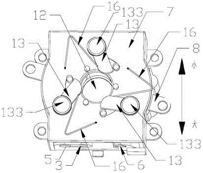
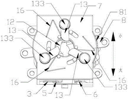
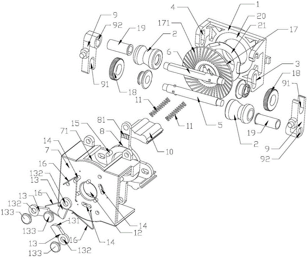
[0022] Embodiment 1: As shown in the figure, a pen feeding mechanism suitable for pencils of any specification includes a bracket 1, two installation shafts arranged in parallel and at intervals, two pen feeding wheels 2 and a mechanism for driving the two installation shafts to rotate. Drive mechanism, two pen feeding wheels 2 are sleeved on two installation shafts one by one, the outer surface of the middle part of each pen feeding wheel 2 is recessed to form a clamping surface, and the center of the bracket 1 is symmetrically provided with a first bar-shaped groove 3 and the second bar-shaped groove 4, the two installation shafts are the first installation shaft 5 and the second installation shaft 6, one end of the first installation shaft 5 is located in the first bar-shaped groove 3 and can be stressed in the first bar-shaped Move in the slot 3, the other end of the first installation shaft 5 is pivotally connected to the bracket 1, one end of the second installation shaft...

Embodiment 2

[0028] Embodiment 2: As shown in the figure, a pen feeding mechanism suitable for pencils of any specification includes a bracket 1, two installation shafts arranged in parallel and at intervals, two pen feeding wheels 2 and a mechanism for driving the two installation shafts to rotate. Drive mechanism, two pen feeding wheels 2 are sleeved on two installation shafts one by one, the outer surface of the middle part of each pen feeding wheel 2 is recessed to form a clamping surface, and the center of the bracket 1 is symmetrically provided with a first bar-shaped groove 3 and the second bar-shaped groove 4, the two installation shafts are the first installation shaft 5 and the second installation shaft 6, one end of the first installation shaft 5 is located in the first bar-shaped groove 3 and can be stressed in the first bar-shaped Move in the slot 3, the other end of the first installation shaft 5 is pivotally connected to the bracket 1, one end of the second installation shaft...


PUM


Abstract

The invention discloses an automatic pencil feeding mechanism suitable for pencils of various specifications. The automatic pencil feeding mechanism comprises a support, two mounting shafts arranged in parallel in a spaced manner, two pencil conveying wheels and a drive mechanism for driving the two mounting shafts to rotate. The support is provided with a first strip-shaped groove and a second strip-shaped groove which are in central symmetry. The two mounting shafts are the first mounting shaft and the second mounting shaft respectively. One end of the first mounting shaft is located in the first strip-shaped groove and can move in the first strip-shaped groove when stressed. The other end of the first mounting shaft is connected to the support through a shaft. One end of the second mounting shaft is connected to the support through a shaft. The other end of the second mounting shaft is located in the second strip-shaped groove and can move in the second strip-shaped groove when stressed. The pencil feeding mechanism further comprises a spacing adjustment assembly. The spacing adjustment assembly is used for driving the first mounting shaft to move in the first strip-shaped groove and the second mounting shaft to move in the second strip-shaped groove. The automatic pencil feeding mechanism has the beneficial effects that pencil feeding holes can be adjusted in an adaptive manner according to the specifications of pencils and the pencil feeding mechanism is suitable for automatic feeding of pencils of various specifications.

Description

technical field [0001] The invention relates to a pen feeding mechanism, in particular to an automatic pen feeding mechanism suitable for pencils of any specification. Background technique [0002] The automatic pen-feeding mechanism of existing pencil sharpener mainly comprises support, two installation shafts, two pen delivery wheels and the drive mechanism that is used to drive two installation shafts to rotate, two installation shafts are arranged on the support in parallel at intervals, two The two pen feed wheels are installed on the two installation shafts one by one, the outer surface of the middle part of each pen feed wheel is sunken to form a clamping surface, and a pen entry hole is formed between the clamping surfaces of the two pen feed wheels. The pencil enters from the pen feeding hole and is clamped by the clamping surface of the two pen feeding wheels. The driving mechanism drives the two installation shafts to rotate so that the two pen feeding wheels move...

Claims


Application Information

Patent Timeline
IPC IPC(8): B43L23/02
Inventor 金响标
Owner YIWU DINGBANG STATIONERY & SPORTING GOODS
Why Eureka
Try Eureka