Pulley frame for aircraft slat rails

A pulley frame and slat technology, applied in the field of pulley frames, can solve the problems that the position of the bolts cannot be fixed and locked, and the eccentric bushing can not be adjusted at the same time, so as to achieve the effect of simple structure and convenient operation

Active Publication Date: 2019-01-22
COMAC +1
View PDF7 Cites 4 Cited by
  • Summary
  • Abstract
  • Description
  • Claims
  • Application Information

AI Technical Summary

Problems solved by technology

[0009] It can be seen that the patent application protects the auxiliary lifting surface control mechanism, which also uses the eccentric bushing 140 to adjust, but the radial bolt assembly designed by it does not involve the cooperation and locking between the bushing and the bolt, and cannot guarantee the adjustment. At the same time, the eccentric bushings at the head and tail of the bolt are adjusted at the same time, and there is no locking piece at the head of the bolt. After the slide rail is adjusted, the fixing and locking of the bolt position cannot be guaranteed.

Method used


Image

  • Pulley frame for aircraft slat rails
  • Pulley frame for aircraft slat rails
  • Pulley frame for aircraft slat rails

Examples


Embodiment Construction

[0079] The present invention will be further described below in conjunction with the accompanying drawings and embodiments, so as to more clearly connect the inventive principle and beneficial technical effects of the present invention.

[0080] Explanation of terms used in this article:

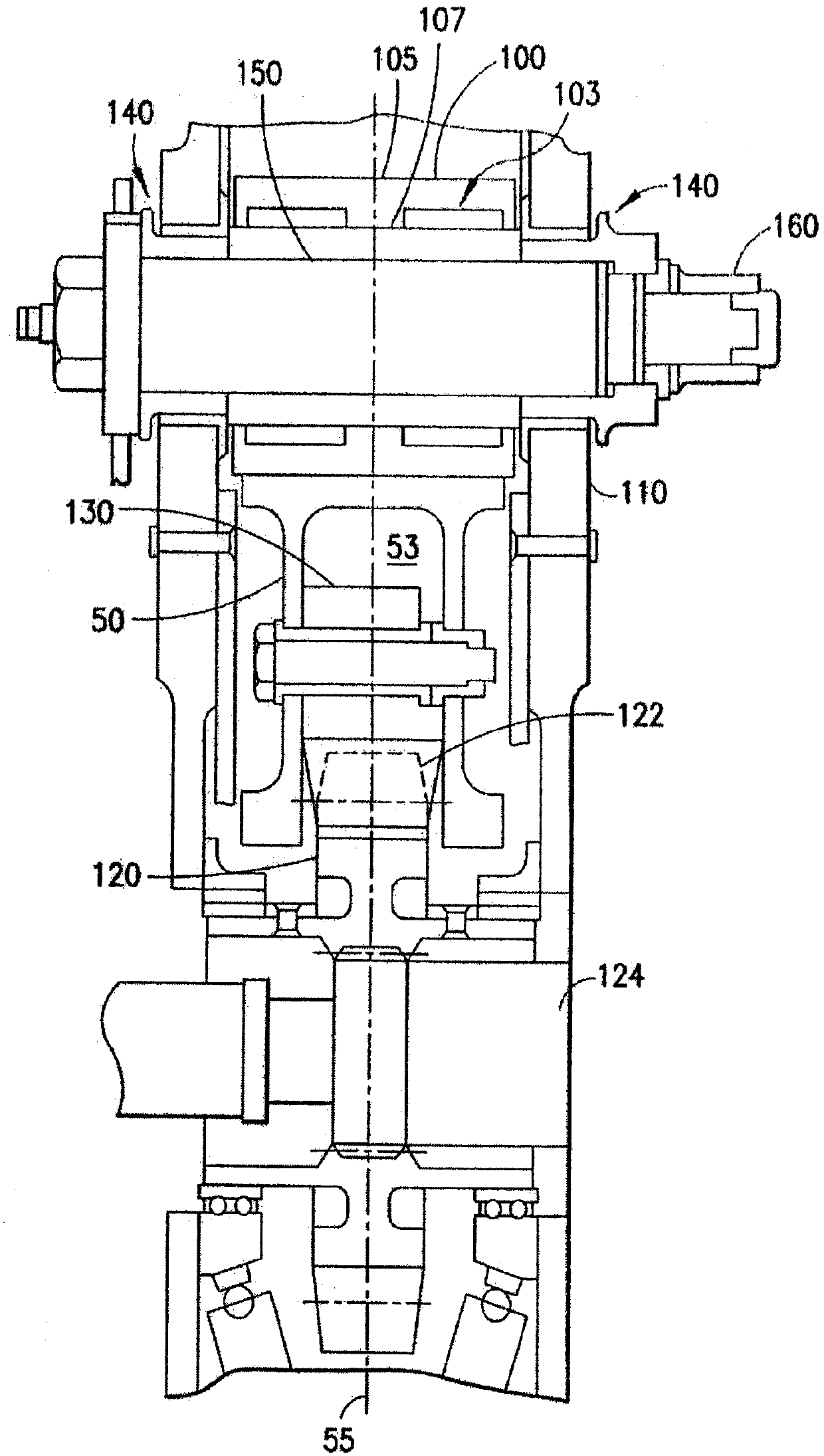
[0081] exist Figure 4 The top of the slat slide rail 9 is called upper;

[0082] exist Figure 4 The bottom of the slat slide rail 9 is called the bottom;

[0083] Along the longitudinal direction of the slat slide rail 9, adjacent to the leading edge of the slat is referred to as the front;

[0084] Along the longitudinal direction of the slat rail 9, relative to the leading edge of the slat is referred to as rear.

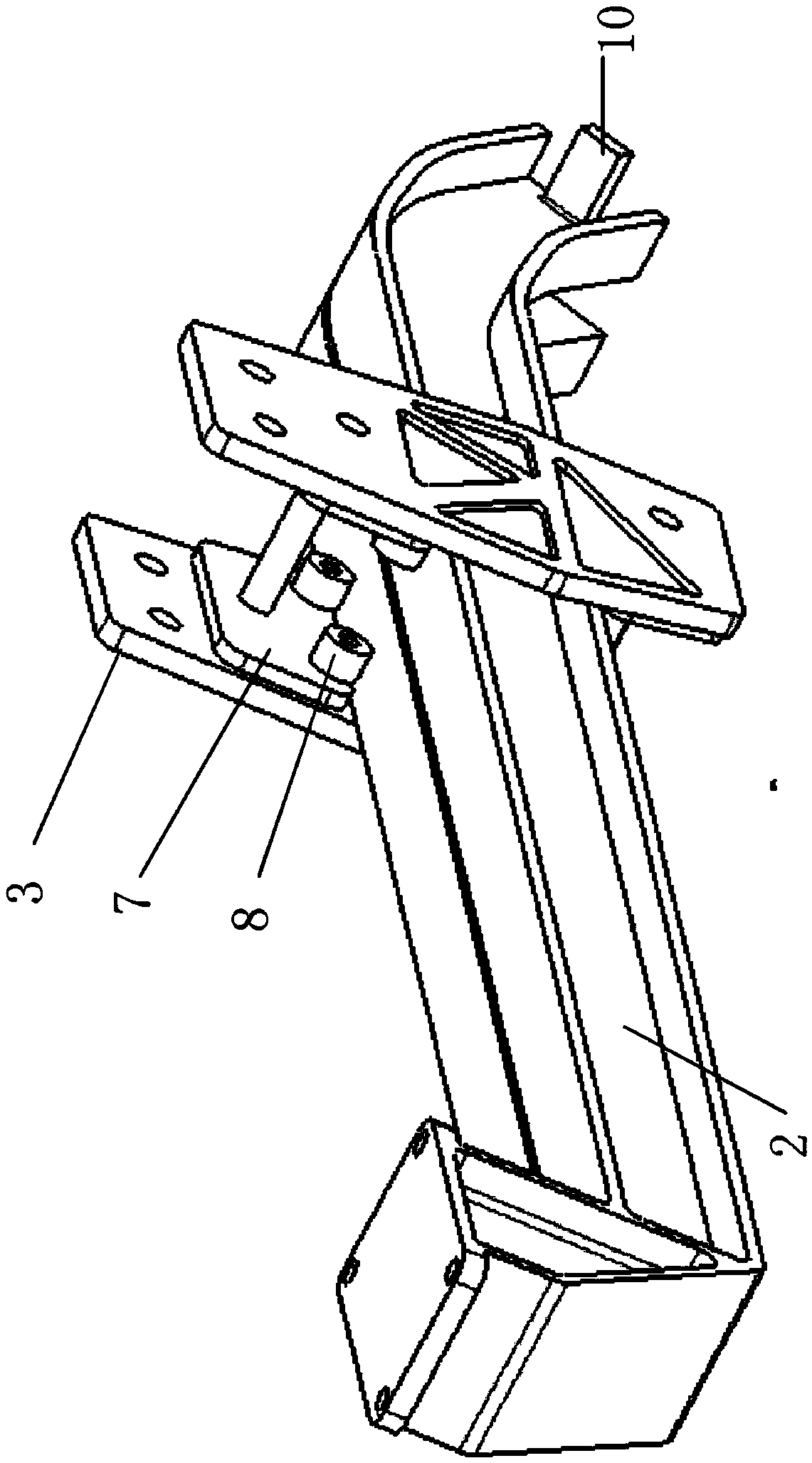
[0085] like Figure 4 As shown, it shows the structure of the pulley frame 10 and the slat slide rail 9 according to the present invention and the mating relationship after the two are assembled. The pulley frame 10 includes a pair of reinforced bulkheads 1 and two pairs...


PUM


Abstract

The invention provides a pulley frame for an aircraft slat rail. The pulley frame comprises a pair of reinforcing partitions, and the slotted-wing slide rail slides between the pair of reinforcing partitions. At least two pairs of radial rollers and bolt assemblies; and a stop. The radial roller and bolt assembly on the upper side of the slat rail further includes a pair of eccentric bushings supported on both end portions of the bolt shank, and the radial bolts are supported on a pair of reinforcing baffles by a pair of eccentric bushings so that the radial roller can rotate relative to the reinforcing baffles; a stop couples a pair of eccentric bushings to the radial bolts to prevent rotation of the radial bolts relative to the pair of eccentric bushings.

Description

technical field [0001] The invention relates to a pulley frame used for aircraft slat slide rails, in particular to a radial bolt assembly supporting radial rollers in the pulley frame. Background technique [0002] Due to the narrow space at the leading edge of the wing, it is impossible to arrange a control mechanism similar to the slat slide rail. The slat generally adopts the form of fixed axis rotation to realize the movement between different configuration states. A single slat is supported in the leading edge compartment by 2 or 3 arc-shaped slide rails. All slat slide rails are supported on the pulley frame in the leading edge compartment by 2 pairs of radial rollers and 2 pairs of lateral rollers. The active slat slide rail in the slide rail is "π" type, a groove is formed in the middle of the slide rail to install the rack, and notches are formed on both sides of the slide rail. The pulley frame consists of 2 pairs of radial rollers, 2 pairs of lateral rollers an...

Claims


Application Information

Patent Timeline
Patent Type & Authority Applications(China)
IPC IPC(8): B64C9/02B64C9/22
CPCB64C9/02B64C9/22
Inventor 张元卿万龙何瑞柯志强刘力搏李明
Owner COMAC
Why Eureka
Try Eureka