A lockable CD box

An optical disc box and locking technology, applied in the field of optical disc storage, can solve the problems of disc wear, damage, loss of information, etc., and achieve the effect of improving the stability of transportation and improving the safety.

Active Publication Date: 2017-06-30
SUZHOU NETZON INFORMATION STORAGE TECH
View PDF3 Cites 0 Cited by
  • Summary
  • Abstract
  • Description
  • Claims
  • Application Information

AI Technical Summary

Problems solved by technology

[0003] In the prior art, the common disc case is only provided with a mechanism for locking the disc tray in the disc case, but it cannot completely prevent the disc tray from shaking in the disc case, nor can it prevent the disc from moving in the disc case. Happening
During the transportation of the disc or when the disc box is subjected to a huge impact, the disc in the disc case is prone to shift, resulting in wear or damage of the disc, which will eventually lead to a huge loss of information loss

Method used


Image

  • A lockable CD box
  • A lockable CD box
  • A lockable CD box

Examples


Embodiment 1

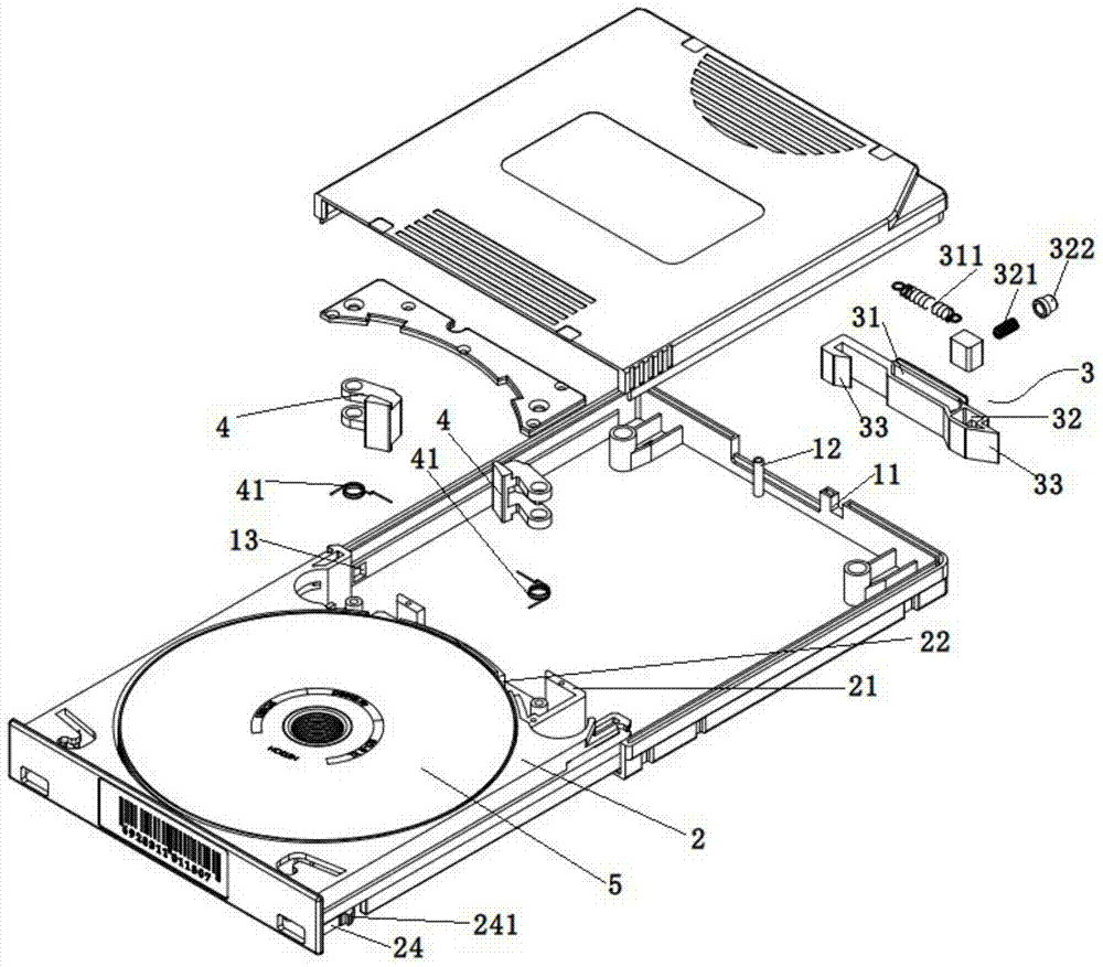
[0026] Example 1: figure 1 It is a schematic exploded view of the structure of the lock type optical disc case provided by the embodiment of the present invention. It can be clearly seen from the figure that the lock type optical disc case provided by this embodiment includes a case body 1 with an opening at the front end and a case body 1 arranged on the case body. The disc tray 2 in 1, the middle part of the disc tray 2 is provided with a coil for supporting the disc 5, and it is characterized in that, the disc tray 2 is provided with a disc clamping part 4, and the disc clamping part 4 is close to The coil, the box body 1 is provided with a tray locker 3, the tray locker can slide between the locked position and the unlocked position, and the tray locker 3 is moved to make it in the locked position , the tray locking member 3 drives the disc clamping member 4 to move toward the coil, so that the optical disc 5 is clamped in the coil, and when the tray locking member 3 is mo...

Embodiment 2

[0034] Embodiment 2: As the best implementation mode of the tray locker 3 in embodiment 1, it is convenient for the tray locker 3 to move between the locked position and the unlocked position, and the tray locker 3 includes a first locker slot 31 and the second locking groove 32, the first elastic member 311 is housed in the first locking groove 31, the second elastic member 321 is housed in the second locking groove 32, and the second elastic member 321 One end is fixedly connected to a locking member 322, and a positioning column 12 is fixedly arranged on the inner side wall of the box body 1, and the positioning column 12 is located in the first locking groove 31, and one end of the first elastic member 311 is connected to the The positioning column 12 is connected, and the other end is fixed on the inner side wall of the first locking groove 31. When the tray locking member 3 is in the unlocked position, the first elastic member 311 does not deform, and the The second elas...

Embodiment 3

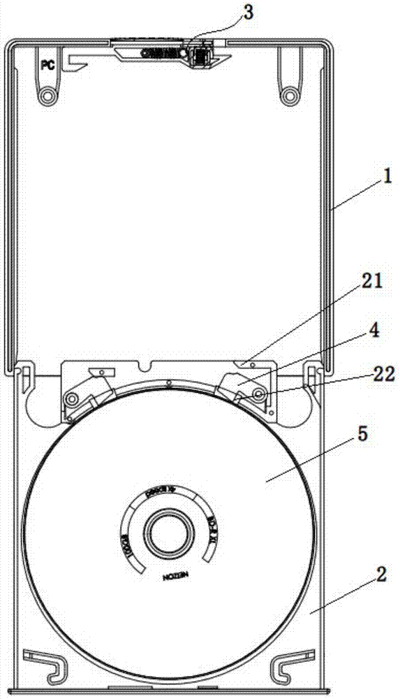
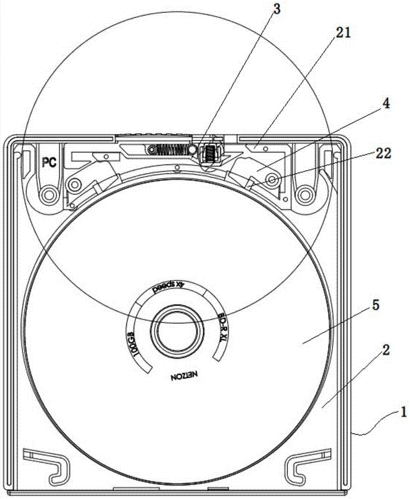
[0036] Embodiment 3: Different from Embodiment 1, the disc tray 2 is provided with a limit strip 21 that cooperates with the tray locker 3. When the tray locker 3 is in the locked position, the The tray locker 3 is engaged with the limit bar 21 , and when the tray locker 3 is in the unlocked position, the tray locker 3 is separated from the limit bar 21 . On the one hand, when the tray locking member 3 is engaged with the limiting bar 21, the tray locking member 3 moves between the limiting bar 21 and the disc clamping member 4, and the limiting bar 21 can make the tray The locking member 3 moves smoothly along the limit bar to enhance the pressing force of the tray locking member 3 on the disc clamping member 4; Snapping into the locking groove 13 on the box body can prevent the disc tray 2 from being pulled out from the box body 1, and in addition, the engagement of the tray locking member 3 and the limit bar 21 on the disc tray 2 in this embodiment The cooperation can ensu...


PUM


Abstract

The present invention relates to the field of optical disk storage, and discloses a lock-type optical disk box, which includes a box body with an opening at the front end and an optical disk tray arranged in the box body. The disc tray is provided with a disc clamping part, the disc clamping part is close to the disk ring, and the tray locker is provided on the box body, and the tray locker can be between the locked position and the unlocked position. Sliding, when the tray locker is in the locked position, the tray locker drives the disc clamping member to move towards the coil, so that the disc is clamped in the coil, when the tray locker When in the unlocked position, the disc clamping member does not press the edge of the disc. The locking type disc box of the present invention has a simple structure, protects the disc, ensures the absolute stillness of the disc tray and the disc in the disc case, and improves the safety of disc storage and the stability of transportation.

Description

technical field [0001] The invention relates to the field of optical disk storage, in particular to a locking type optical disk box. Background technique [0002] In the existing optical disc storage technology, optical disc boxes are usually used to store and transport optical discs. There is a pullable optical disc tray inside the optical disc case, and the optical disc tray can be pulled out to the outside of the optical disc case to grab the optical disc tray and load it CD, or put the CD into the CD tray and then push the CD tray to the inside of the CD box to complete the storage of the CD. [0003] In the prior art, the common disc case is only provided with a mechanism for locking the disc tray in the disc case, but it cannot completely prevent the disc tray from shaking in the disc case, nor can it prevent the disc from moving in the disc case. Condition. During the transportation of the optical disc or when the optical disc case is subjected to a huge impact, the...

Claims


Application Information

Patent Timeline
Patent Type & Authority Patents(China)
IPC IPC(8): B65D55/10B65D85/57
Inventor 朱明邵征宇许长江徐宏
Owner SUZHOU NETZON INFORMATION STORAGE TECH
Why Eureka
Try Eureka