Safety hanging locking device for draw circuit breaker

A circuit breaker and withdrawable technology, which is applied in the field of padlock devices of withdrawable circuit breakers, to achieve the effect of ensuring correctness

Inactive Publication Date: 2004-07-28
常熟开关制造有限公司
View PDF1 Cites 0 Cited by
  • Summary
  • Abstract
  • Description
  • Claims
  • Application Information

AI Technical Summary

Problems solved by technology

This utility model patent only solves the problem of the interlock between the handle and the

Method used


Image

  • Safety hanging locking device for draw circuit breaker
  • Safety hanging locking device for draw circuit breaker

Examples


Embodiment Construction

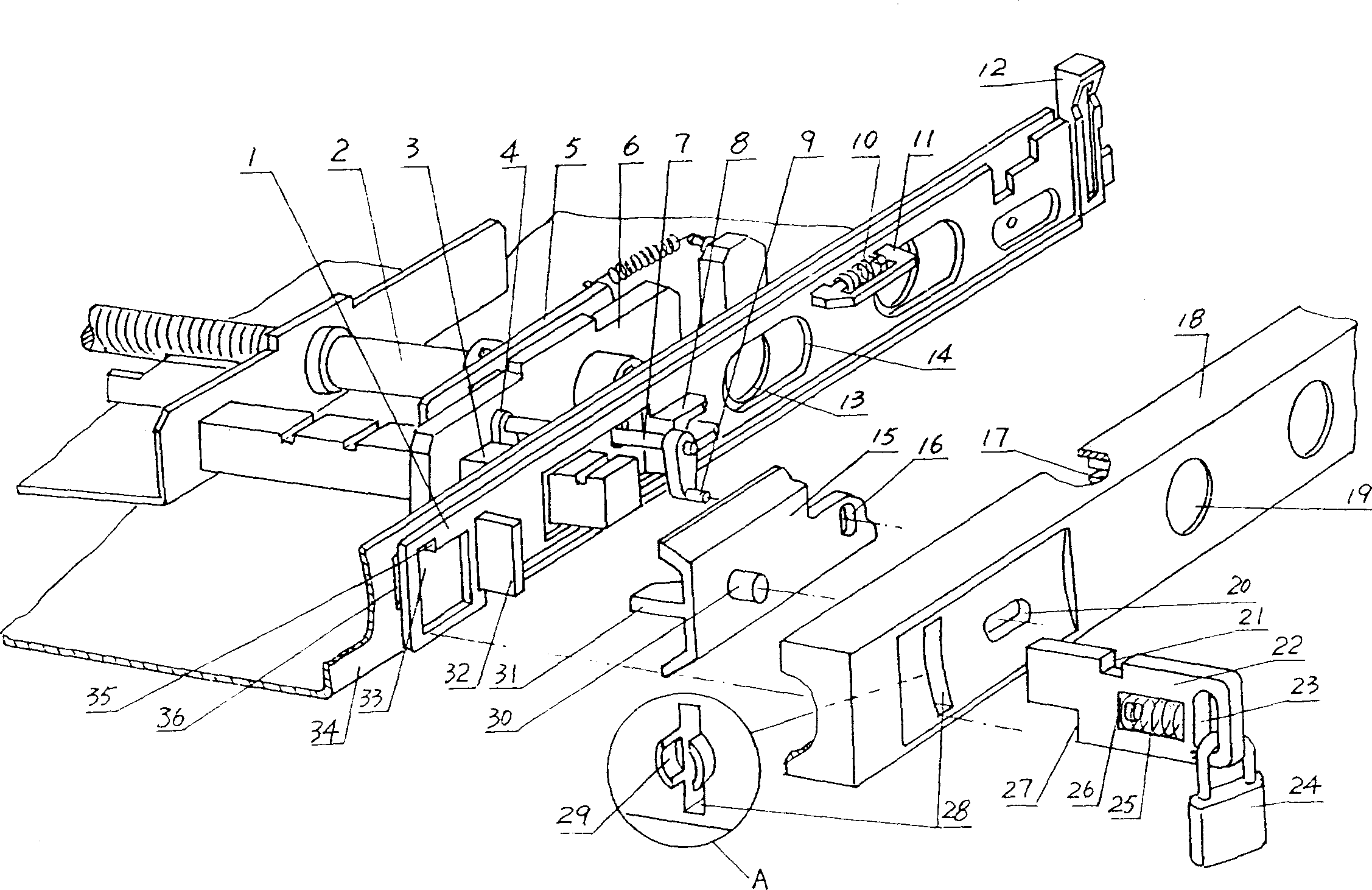
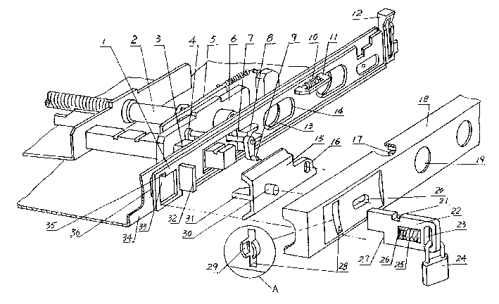
[0010] The fixed cover 18 of the present invention is in the shape of a Ц-shaped box, and the front panel of the fixed cover 28 is respectively provided with a lock piece hole 28, a button hole 20, a handle jack 19 and an analog indicator installation hole. The back side is respectively shaped on spring seat 29, spring seat groove 17. The fixed cover 18 is installed on one side of the circuit breaker base plate 34 , and the handle insertion hole 19 on it is aligned with the handle insertion hole 13 on the base plate 34 .

[0011] The lock plate 1 of the present invention has a padlock piece groove 33, a boss 35, a limit plate 32, a square shaft 3 and a mounting hole for a shift fork shaft 7, a bevel 8, a handle jack 14, a return spring 10, and a spring seat 11. The analog indicator installation hole, the protrusion 12, the lock plate 1 is embedded in the seat cavity at the bottom of the fixed cover 18, and can move left and right in the seat cavity. During installation, the ha...


PUM


Abstract

The invented device includes the fixed cover, the locking plate, the padlock plate, the padlock and the unlocking button. The fixed cover is mountedon the side of the circuit breaker board. The slidable locking plate with the return spring is setup in the fixed cover. With being mounted in the fixed cover, the slidable padlock plate passing through the locking plate and the slot of the padlock plate is limited on the board. The return spring also mounted on the padlock plate. When the padlock plate is drawn out outward, the padlock is locked on the padlock plate. The slidable unlocking button is mounted in the fixed cover. The stopper is extended from the unlocking button. The plate for limiting position is extended from the locking plate to lock the unlocking button.

Description

technical field [0001] The invention relates to a padlock device of a withdrawable circuit breaker, in particular to an improvement to the existing padlock device of a withdrawable circuit breaker. Background technique [0002] The safety padlock device of the existing withdrawable circuit breaker comprises a fixed cover, a lock plate, a padlock piece, and a padlock. Return spring, the return spring makes the lock plate always be pushed to the right, the padlock piece is slidably arranged in the fixed cover, and a return spring is also installed on it, the return spring makes the padlock piece always receive the backward thrust , the padlock piece passes through the fixed cover, the lock plate and the slot hole on the bottom plate in sequence, and is limited on the bottom plate by the step at its lower end, and the groove at the upper end of the padlock piece is aligned with the boss in the slot hole of the lock plate, The lock plate can move left and right in the fixed cov...

Claims


Application Information

Patent Timeline
IPC IPC(8): H02B11/12H02B11/127
Inventor 管瑞良俞晓峰钱锦丰
Owner 常熟开关制造有限公司
Why Eureka
Try Eureka