Control valve

A technology of regulating valve and valve head, applied in the field of regulating valve, can solve problems such as expensive, and achieve the effects of reduced risk, high reliability, and simple cleaning

Active Publication Date: 2019-08-06
GEZE GMBH
View PDF5 Cites 0 Cited by
  • Summary
  • Abstract
  • Description
  • Claims
  • Application Information

AI Technical Summary

Problems solved by technology

To avoid this, additional brake and sealing rings are usually installed, but this is extremely expensive

Method used


Image

  • Control valve
  • Control valve
  • Control valve

Examples


Embodiment Construction

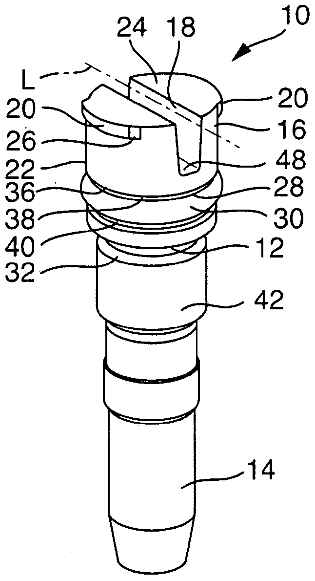
[0023] figure 1 An exemplary embodiment of a control valve 10 according to the invention for actuating devices such as doors or windows is shown schematically, with a valve body 12 made of plastic, in particular an injection molded part, and a valve Section 14 , which in particular can be produced from the same material as valve body 12 and can be formed in one piece with it. In the present case the valve section 14 is arranged, for example, in the form of a valve cone.

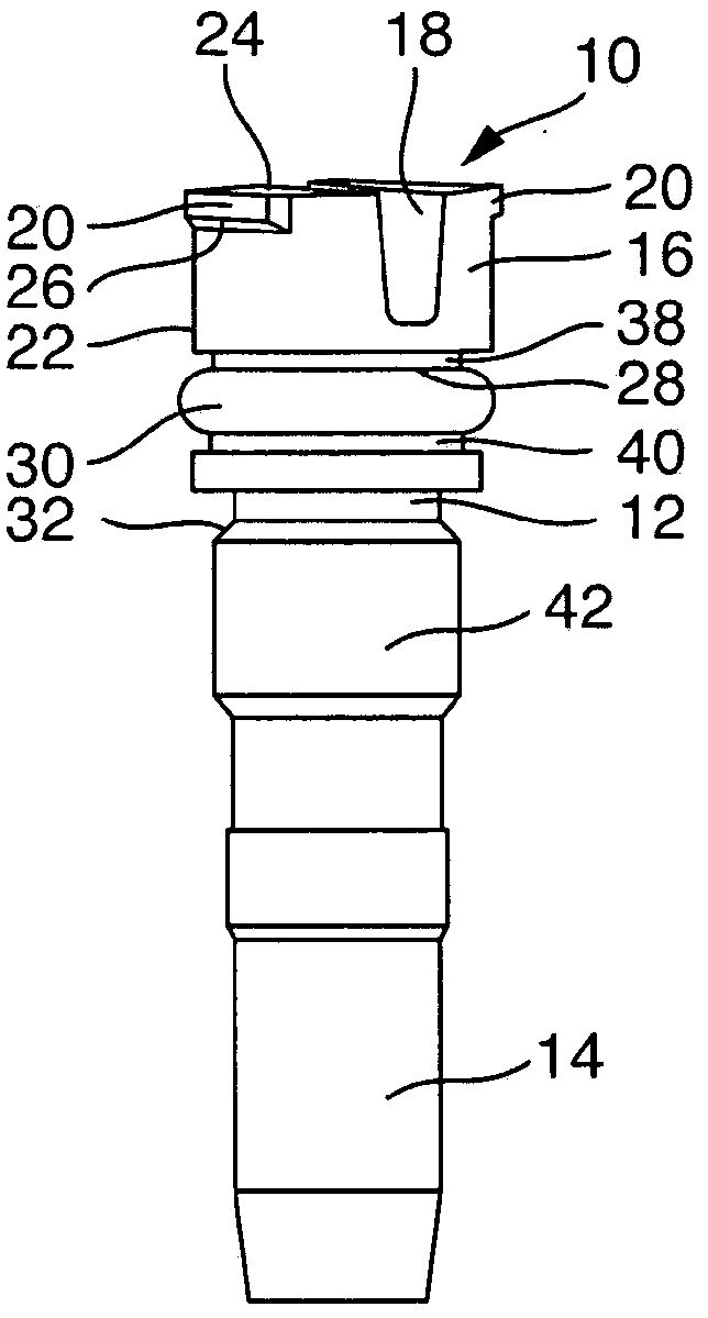
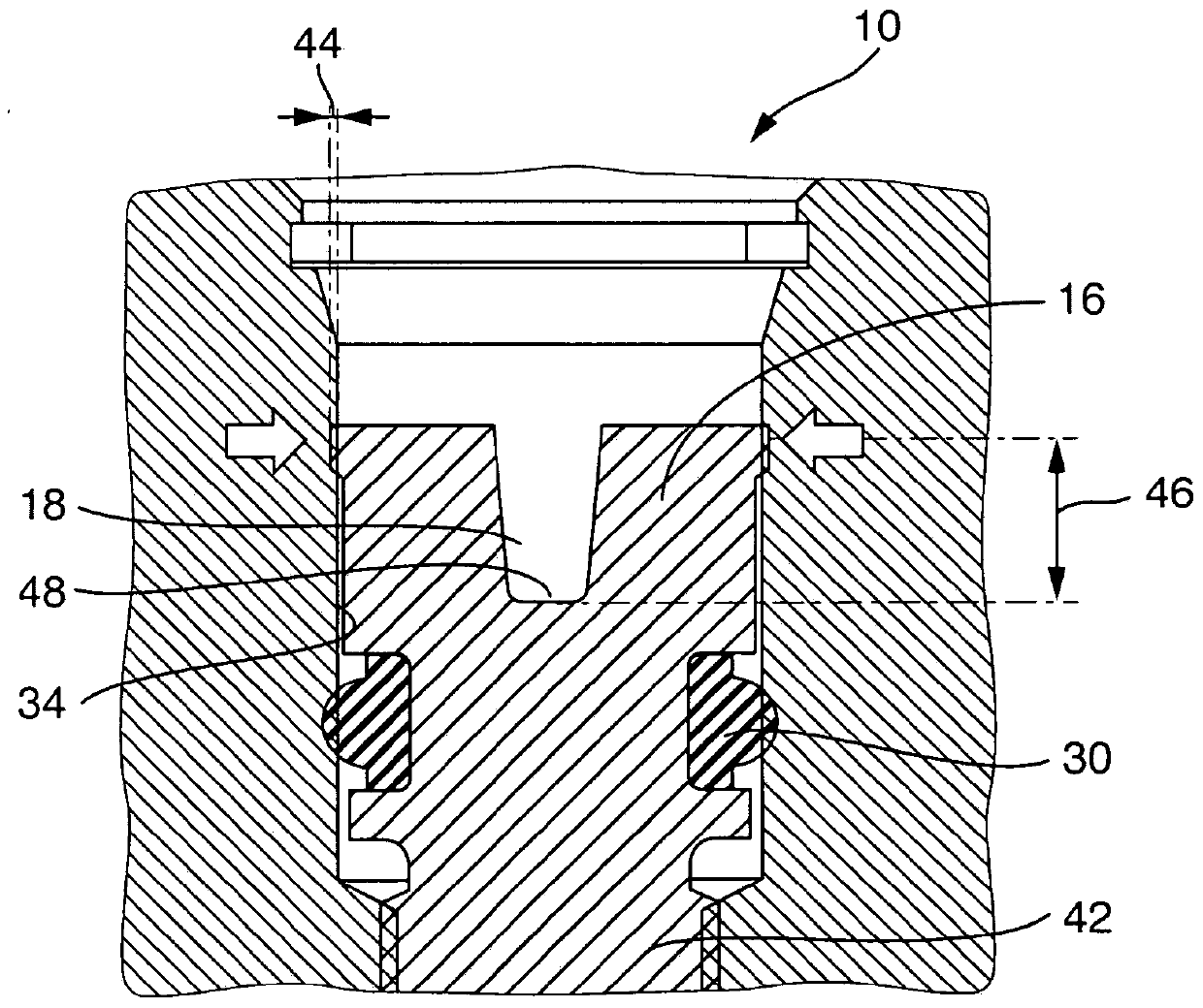
[0024] The valve body 12 includes a valve head 16 which is provided with a tool receptacle in the form of an elongated slot 18 extending transversely through the valve head for an operating tool, such as a screwdriver or the like. The valve head 16 is provided on its periphery with a pretensioning flank 20 which extends radially outward transversely to the longitudinal direction L of the slot 18 .

[0025] In this case, the valve head 16 is provided, for example, in the present case with two opposing preten...


PUM


Abstract

The invention relates to a control valve used for a driving device of a door or a window, comprising in particular a valve body prepared by plastics and a valve section set in a valve tapper form. The valve body comprises a valve head provided with a tool accommodating portion used for operating tools. Besides, the tool accommodating portion is configured to be a slit horizontally extending and penetrating the valve head; the valve head is provided with a pretightening side wing on the periphery, the pretightening side wing radially extending outwards in a mode of paralleling with the slit.

Description

technical field [0001] The invention relates to a control valve for a drive device, in particular for a door or a window, comprising a valve section and a valve body, in particular made of plastic, wherein the valve body comprises a valve head, which is arranged There is a tool holder for handling tools. Background technique [0002] Drives for doors or windows are known and can be designed as manual or automatic drives. Such drives are known to comprise a housing provided with a bore in which a working piston is arranged, which interacts with the output shaft in the manner of a transmission. A pull rod or a slide arm can be arranged on the driven shaft in a non-rotatable manner. The drive device can optionally be arranged on the door or window leaf or on its frame. Correspondingly, the tie rod or sliding arm is supported on the frame or the leaf, thereby realizing the connection between the pivotal movement of the leaf and the drive. [0003] In addition, a spring is pr...

Claims


Application Information

Patent Timeline
Patent Type & Authority Patents(China)
IPC IPC(8): F16K1/34F16K1/46
CPCF16K1/04E05F3/12
Inventor B·韦尔纳
Owner GEZE GMBH
Why Eureka
Try Eureka