Motor

A motor and casing technology, applied in the field of motors, can solve the problems of the bus bar cage being not firmly fixed, generating vibration or noise, reducing the service life of the motor, etc. Effect

Active Publication Date: 2016-02-03
NIDEC CORP
View PDF6 Cites 10 Cited by
  • Summary
  • Abstract
  • Description
  • Claims
  • Application Information

AI Technical Summary

Problems solved by technology

Therefore, for example, if the bus bar holder heat-shrinks at a low temperature, a gap is formed between the case and the bus bar holder, and the fixation of the bus bar holder becomes weak.
As a result, there is a concern that vibration or noise is generated when the motor is driven, reducing the service life of the motor

Method used


Image

  • Motor
  • Motor
  • Motor

Examples


no. 1 approach >

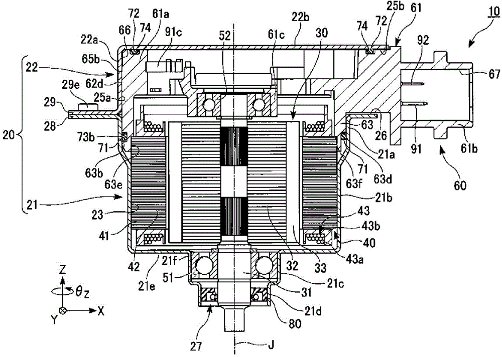
[0025] figure 1 It is a cross-sectional view showing the motor 10 of this embodiment.

[0026] The motor 10 of this embodiment is a brushless motor. Such as figure 1 As shown, the motor 10 includes a housing portion 20, a rotor 30 having a shaft 31, a stator 40, a bus bar unit 60, a plurality of O-rings, a front bearing (first bearing) 51, a rear bearing (second bearing) 52, and Oil seal 80. The plurality of O-rings includes a front O-ring (first O-ring) 71 and a rear O-ring (second O-ring) 72.

[0027] [Chassis Department]

[0028] The housing part 20 is a cylindrical metal member in which the bus bar unit 60 is press-fitted inside. The cabinet part 20 has a front cabinet part (first cabinet part) 21 and a rear cabinet part (second cabinet part) 22. The rotor 30, the stator 40, the bus bar unit 60, the front bearing 51, the rear bearing 52, the front O-ring 71, the rear O-ring 72, and the oil seal 80 are held inside the casing portion 20.
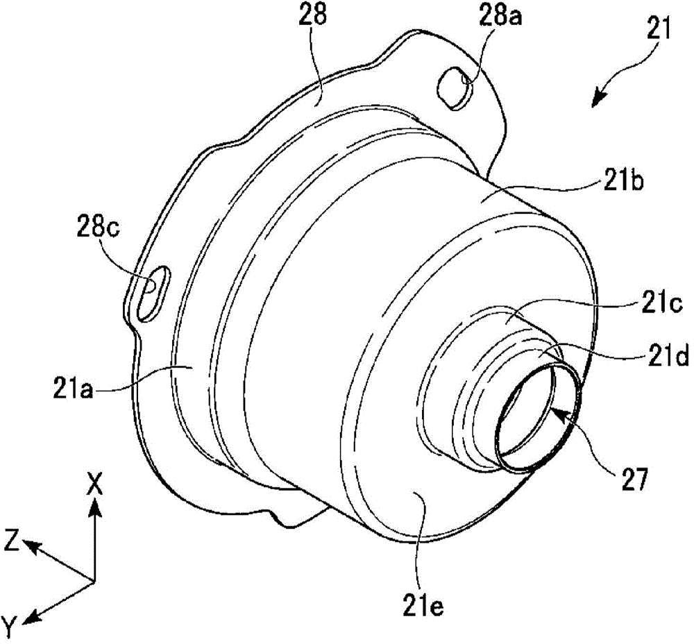
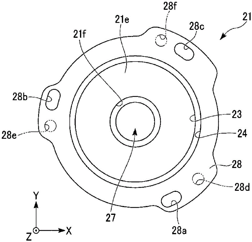
[0029] (Front case)

[0030] Figure 2 t...

no. 2 approach >

[0170] The second embodiment is different from the first embodiment in that the main body has a protrusion group.

[0171] In addition, regarding the same configuration as the first embodiment, the description may be omitted by appropriately attaching the same reference numerals.

[0172] Figure 13 with Figure 14 It is a diagram showing the bus bar unit 260 of this embodiment. Figure 13 It is a three-dimensional view. Figure 14 It is a top view.

[0173] The bus bar unit 260 has a bus bar holder 261. The bus bar holder 261 has a main body portion 261a. The main body 261a has a plurality of protruding part groups (contact part groups). In this embodiment, there are three or more protrusion groups. As an example, in Figure 14 An example is shown in which three groups of protrusions (contact part groups) 267a, 267b, and 267c are provided as a plurality of protrusion groups.

[0174] The protrusion groups 267a, 267b, and 267c are each composed of a plurality of protrusions (contac...


PUM


Abstract

The invention provides a motor which operates stably in a large temperature range. The motor according to one embodiment of the invention comprises a rotor having a shaft, a stator, a first bearing and a second bearing supporting the shaft, a busbar unit, and a metallic housing portion in which the busbar unit is pressed to the inside of housing and the stator and the first bearing are maintained. The busbar unit comprises a busbar and a busbar holder made of resin. The busbar holder supports the busbar and has a second bearing holding portion for holding the second bearing and a tubular main body portion which has a tubular housing portion. The housing portion has a housing accommodating periphery pressed in the housing portion. The motor is characterized in that a contact portion and a non-contact portion are arranged at the periphery of the housing accommodating periphery, the contact portion is in contact with the inner periphery of the housing portion, the contact portion of the housing portion, and the non-contact portion is seperated from the inner periphery of the housing portion.

Description

Technical field [0001] The invention relates to a motor. Background technique [0002] For example, there is known a motor shown in Japanese Laid-Open Publication No. 2009-219335, in which a bearing on one side of a rotating shaft supporting a rotor is held in a bus bar holder, and a bearing on the other side is held in a bus bar housing. The cage of the cage. [0003] In the above-mentioned motor, since the bus bar holder is made of resin, the difference in thermal expansion coefficient between the bus bar holder and the metal casing is large. Therefore, for example, if the bus bar holder thermally shrinks at a low temperature, a gap is generated between the cabinet and the bus bar holder, resulting in unstable fixing of the bus bar holder. As a result, there is a concern that vibration or noise is generated when the motor is driven, and the service life of the motor is reduced. Summary of the invention [0004] One aspect of the present invention is formed in view of the above-...

Claims


Application Information

Patent Timeline
Patent Type & Authority Applications(China)
IPC IPC(8): H02K5/04H02K5/10
CPCH02K5/225H02K3/50H02K5/08
Inventor 芳贺英博佐藤留介
Owner NIDEC CORP
Why Eureka
Try Eureka