
Brake-shoe installation structure

A technology for installing structure and brake shoe, which is applied in transportation and packaging, railway braking system, mechanical equipment, etc., and can solve the problems of unavailability of brake shoe and increased cost.

Active Publication Date: 2012-06-13
NABLESCO CORP
View PDF4 Cites 0 Cited by
  • Summary
  • Abstract
  • Description
  • Claims
  • Application Information

AI Technical Summary

Problems solved by technology

[0005] However, the brake shoe that can be used in the brake shoe mounting structure described in Patent Document 1 and figure 1 Compared with the previously used brake shoe shown, the shape of the part where the brake shoe is locked is different, so the existing brake shoe cannot be used, and a new shape of the brake shoe needs to be produced, which has the problem of increasing the cost.

Method used


Image

  • Brake-shoe installation structure
  • Brake-shoe installation structure
  • Brake-shoe installation structure

Examples


Embodiment Construction

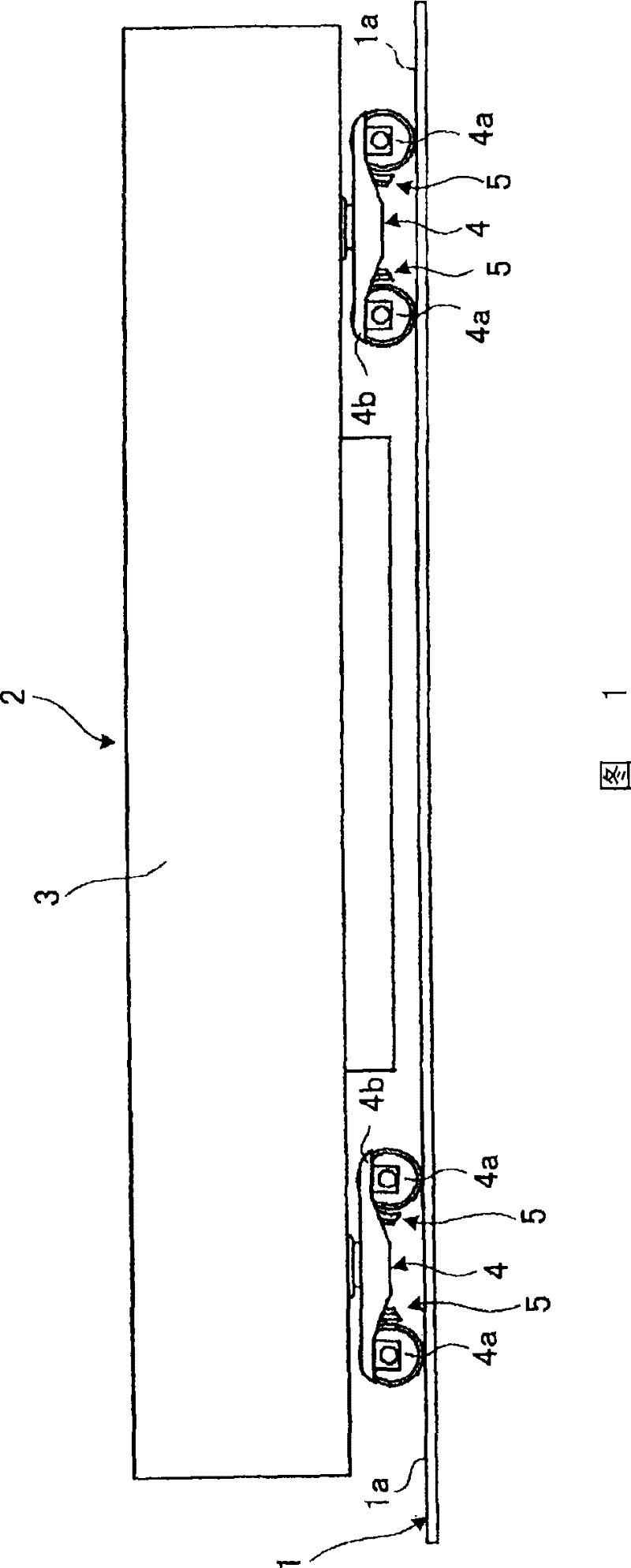
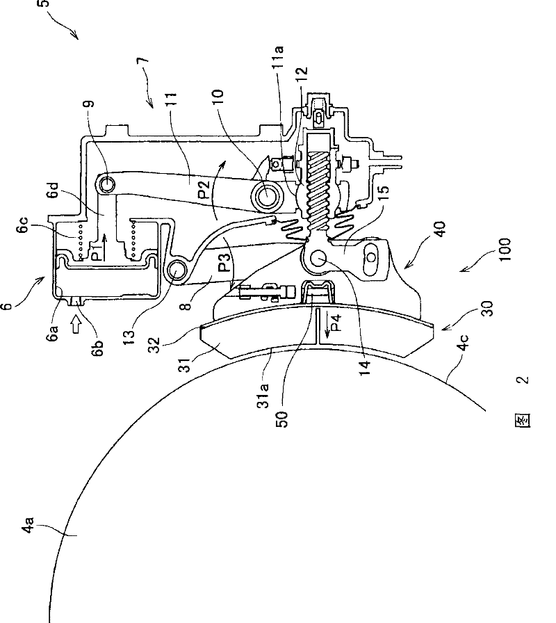
[0057] The best mode for carrying out the present invention will be described below with reference to the drawings. figure 1 It is a side view of a railcar provided with a brake device for a railcar to which the brake shoe mounting structure according to the embodiment of the present invention is applied. figure 2 It is a side view of a railcar brake device to which the brake shoe mounting structure of the present invention is applied.

[0058] figure 1 The illustrated track 1 is a path (route) on which the vehicle 2 travels, and is constituted by guide rails 1 a for supporting and guiding the vehicle 2 , and the like. The vehicle 2 is a rail vehicle such as an electric train or a diesel train, and includes a car body 3 , a bogie 4 , a brake device 5 to which a brake shoe mounting structure 100 is applied, and the like. The vehicle body 3 is a structure for loading and transporting passengers, and the trolley 4 is a device that supports the vehicle body 3 and travels. The ...


PUM


Abstract

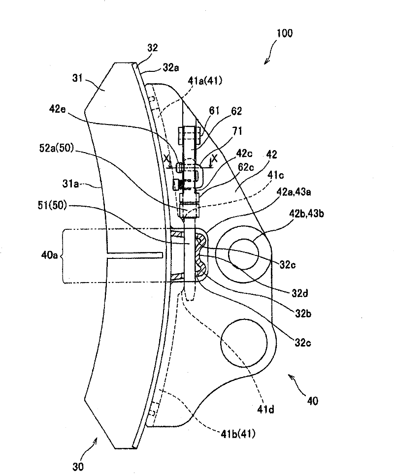
A brake-shoe installation structure where a brake-shoe head (40) has an insertion opening (42c) formed as an elongate hole so that an L-shaped brake-shoe cotter (50) having a bend (52a) can be inserted through the insertion opening from the direction of the rotation axis of a wheel. A brake shoe (30) has an installation section (32b) that is inserted in an installation opening (40a) of the brake-shoe head (40). The brake-shoe cotter (50) is inserted from the insertion opening (42c) into an installation hole (32c) in the installation section (32b) of the brake-shoe (30), and the brake-shoe (30) can be fixed to the brake-shoe head (40). Also, a first lock member (62) rockably supported at one end at the brake-shoe head (40) is caused to rock so as to be in contact with the bend (52a), and this restricts displacement of the brake-shoe cotter (50) to the upper edge side of the insertion opening (42c). In the brake-shoe installation structure, an existing brake-shoe can be used and a brakeshoe can be replaced easily.

Description

technical field [0001] The present invention relates to a brake shoe mounting structure, the brake shoe has a mounting portion formed protruding from a mounting surface which is the opposite side of the surface pressed against the tread surface of a wheel of a rail vehicle, the above brake shoe mounting structure is formed by The brake shoe pin is inserted into the installation hole provided on the installation part, and is used for fixing the brake shoe on the brake shoe support. Background technique [0002] Conventionally, as a structure for mounting a brake shoe of a tread brake device for a rail vehicle on a brake shoe holder, the mounting structure of the following Patent Document 1 is known. As shown in FIG. The protruding convex part (mounting part) on the back of the brake shoe is inserted into the concave part of the brake shoe support pivotally supported by the brake lever pin (connection pin for connecting with the hanger and the pressure bar), and then the brake...

Claims


Application Information

Patent Timeline
Patent Type & Authority Patents(China)
IPC IPC(8): B61H1/00F16D49/00F16D65/06
CPCB61H1/00F16D65/062F16D49/00F16D65/06
Inventor 麻野吉雄大家秀幸
Owner NABLESCO CORP
Learn More