Power control circuit of power amplifier

A power amplifier and power control technology, applied in the directions of amplification control, gain control, electrical components, etc., can solve the problems of increasing cost, inability to integrate chips, reducing power amplifier efficiency, etc., to reduce size and cost, high gain, and improve The effect of chip integration

Active Publication Date: 2016-02-03
BEIJING HUNTERSUN ELECTRONICS CO LTD
View PDF3 Cites 11 Cited by
  • Summary
  • Abstract
  • Description
  • Claims
  • Application Information

AI Technical Summary

Problems solved by technology

[0005] In view of this, the present application provides a power control circuit of a power amplifier. On the basis of realizing the power control of the power amplifier, it avoids that the chip can

Method used


Image

  • Power control circuit of power amplifier
  • Power control circuit of power amplifier
  • Power control circuit of power amplifier

Examples


Example Embodiment

[0044] Embodiment one

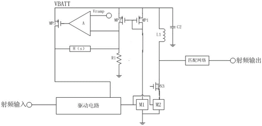
[0045] Embodiment 1 of the present application provides a power control circuit of a power amplifier, such as figure 1 as shown, figure 1It is a schematic diagram of a power control circuit of a power amplifier provided in Embodiment 1 of the present application. The power control circuit includes:

[0046] Composed of the first amplifier tube M1, the second amplifier tube M2, the first P-type MOS tube MP1, the second P-type MOS tube MP2, the first resistor R1, the operational amplifier A, the third P-type MOS tube MP3 and the driving circuit current control loop;

[0047] A voltage control loop composed of the operational amplifier A, the first resistor R1, the third P-type MOS transistor MP3 and the system function circuit H(s);

[0048] The first input end of the driving circuit is the input end of the radio frequency signal, and the output end is connected with the input end of the first amplifier tube M1 and the input end of the second amplifie...

Example Embodiment

[0058] Embodiment two

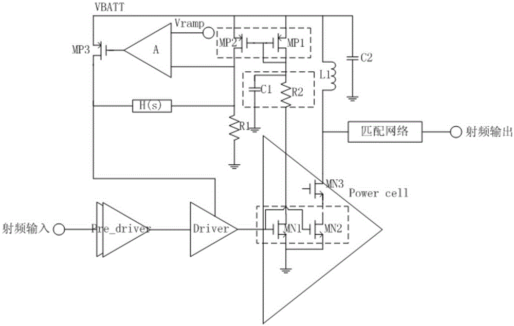
[0059] On the basis of Embodiment 1, Embodiment 2 of the present application provides a more specific power control circuit of a power amplifier, specifically as figure 2 as shown, figure 2 It is a schematic diagram of a power control circuit of a power amplifier provided in Embodiment 2 of the present application. The power control circuit includes:

[0060] Composed of the first amplifier tube M1, the second amplifier tube M2, the first P-type MOS tube MP1, the second P-type MOS tube MP2, the first resistor R1, the operational amplifier A, the third P-type MOS tube MP3 and the driving circuit current control loop;

[0061] A voltage control loop composed of the operational amplifier A, the first resistor R1, the third P-type MOS transistor MP3 and the system function circuit H(s);

[0062] The first input end of the driving circuit is the input end of the radio frequency signal, and the output end is connected with the input end of the first amp...

Example Embodiment

[0085] Embodiment Three

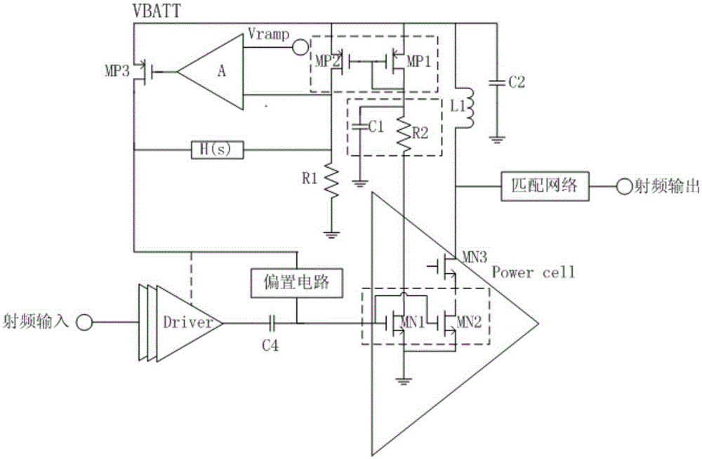
[0086] Embodiment 3 of the present application provides another power control circuit of a power amplifier, specifically as image 3 as shown, image 3 It is a schematic diagram of a power control circuit of a power amplifier provided in Embodiment 3 of the present application. The control circuit includes:

[0087] A voltage control loop composed of the operational amplifier A, the first resistor R1, the third P-type MOS transistor MP3 and the system function circuit H(s);

[0088] The first input end of the driving circuit is the input end of the radio frequency signal, and the output end is connected with the input end of the first amplifier tube M1 and the input end of the second amplifier tube M2 at the same time, and the first amplifier tube M1 is used for sampling the signal of the second amplifier tube M2 current;

[0089] The ground terminal of the first amplifying tube M1 is connected to the ground terminal of the second amplifying tube ...


PUM


Abstract

The application provides a power control circuit of a power amplifier, composed of a current control loop and a voltage control loop, wherein the voltage control loop forms an LDO (Low Dropout Regulator) circuit, requiring no large LDO, or large PMOS pipe for power supply, reducing dimension and cost, and not influencing the power of a power amplifier; the current control loop does not need an accurate Sense sampling resistor, thereby facilitating integration of chips. The power control circuit combines the voltage control technology and the current control technology; before an output circuit starts working and the current control loop is stable, the voltage control loop controls the output power of a power amplifier; then the voltage control loop and the current control loop control the output power of the power amplifier together; and when the current control loop is stable, the current control loop controls the output power of the power amplifier, thereby controlling the output power of the power amplifier from the work beginning of output current to work end.

Description

technical field [0001] The present application relates to the technical field of mobile phone communication, in particular to a power control circuit of a power amplifier. Background technique [0002] In the GSM (Global System for Mobile Communication, Global System for Mobile Communications) system, in order to reduce interference, it is necessary to control the power of the power amplifiers of the base transceiver station BTS and the mobile station MS under the premise of ensuring the level strength and signal quality. In addition, the power control can also prolong the standby time of the mobile phone, and in the case of poor call quality, the transmission power of the mobile phone can be appropriately increased to ensure the call quality. [0003] At present, the power control method of the power amplifier is divided into current control and voltage control. The current control technology is also called the base control technology, which is a closed-loop control. A sma...

Claims


Application Information

Patent Timeline
IPC IPC(8): H03G3/20
Inventor 彭凤雄何世海钱永学孟浩
Owner BEIJING HUNTERSUN ELECTRONICS CO LTD
Why Eureka
Try Eureka