Liquid ejecting head, manufacturing method thereof, and liquid ejecting apparatus

a technology of liquid ejecting head and manufacturing method, which is applied in printing and other directions, can solve the problems of increased manufacturing time and cost, increased head size, and possible electrical conduction defects, and achieve the effect of suppressing overflow of resin and reducing the size of the head

Active Publication Date: 2011-01-27
SEIKO EPSON CORP
View PDF4 Cites 21 Cited by
  • Summary
  • Abstract
  • Description
  • Claims
  • Application Information

AI Technical Summary

Benefits of technology

[0021]In this aspect, since in adjacent through-holes, outflow of resin in one through-hole into the other through-hole can be regulated by the partition wall, it is possible to closely dispose the mounting portions by making positions of adjacent through-holes close

Problems solved by technology

However, if each terminal of the driving circuit is individually connected to each piezoelectric element by wire bonding, the wire bonding must be carried out for as many as the number of piezoelectric elements, so that there is a problem in that manufacturing time and costs increase.
Also, a region for disposing the terminal, to which the bonding wire is connected, needs to be provided at the piezoelectric element, so that there is a problem that the head increases in size.
However, in a case where a row of the piezoelectric e

Method used


Image

  • Liquid ejecting head, manufacturing method thereof, and liquid ejecting apparatus
  • Liquid ejecting head, manufacturing method thereof, and liquid ejecting apparatus
  • Liquid ejecting head, manufacturing method thereof, and liquid ejecting apparatus

Examples


embodiment 1

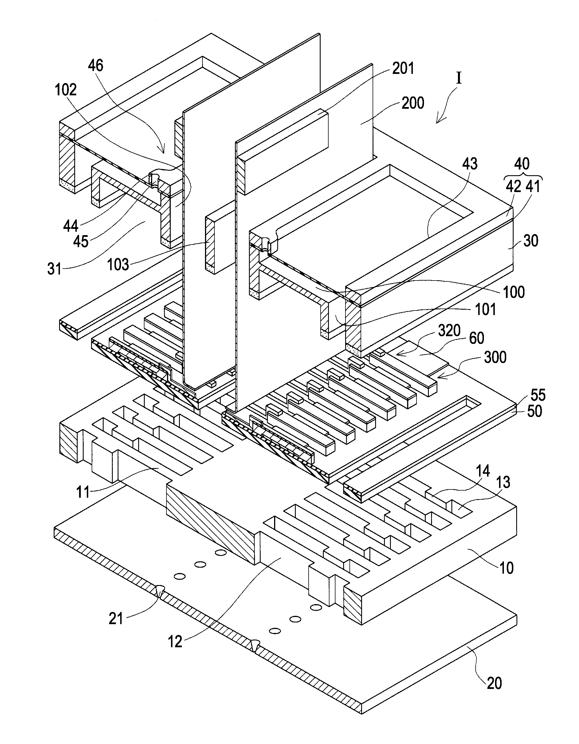
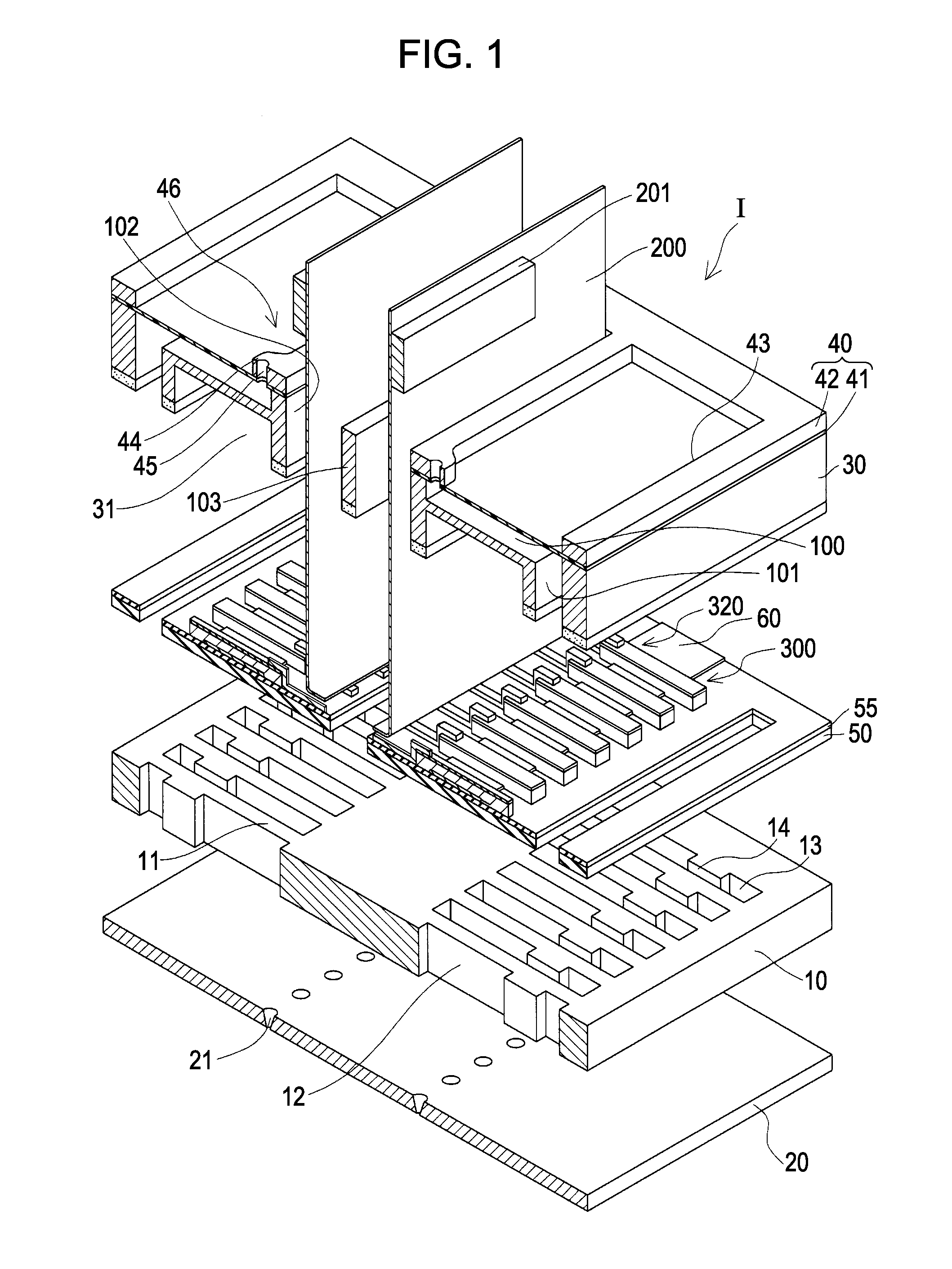
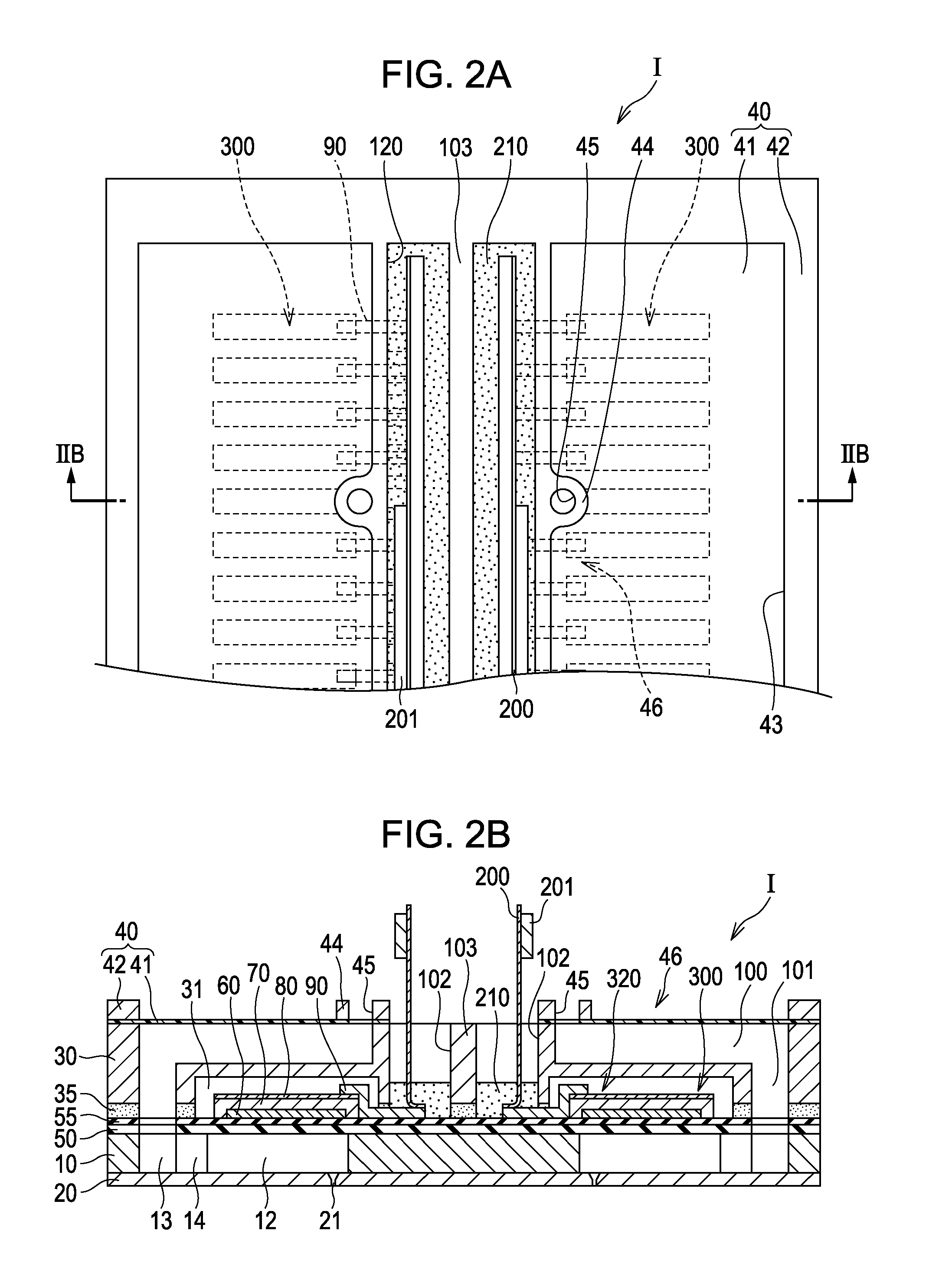
[0032]FIG. 1 is an exploded perspective view showing an ink jet type recording head which is one example of a liquid ejecting head related to Embodiment 1 of the invention, and FIGS. 2A and 2B are a plan view of FIG. 1 and a cross-sectional view taken along line IIB-IIB of FIG. 2A.

[0033]As shown in the drawings, a flow path forming substrate 10 is made of, in this embodiment, a silicon single crystal substrate, and on one face thereof, an elastic film 50 made of silicon dioxide is formed.

[0034]At the flow path forming substrate 10, by performing anisotropic etching from the other face side thereof, a row of pressure generation chambers 12, which are partitioned by a plurality of wall portions 11 and arranged in parallel in the width direction (short side direction) thereof, is provided two rows in the longitudinal direction of the pressure generation chamber 12. Also, on one end side in the longitudinal direction of the pressure generation chamber 12 of the flow path forming substra...


PUM


Abstract

A liquid ejecting head includes: a flow path forming substrate; an actuator device having a plurality of mounting portions provided on the flow path forming substrate; a wiring substrate which has flexibility and is electrically connected to the mounting portions to supply a driving signal to the actuator device; and a protective substrate provided on the mounting portions side of the flow path forming substrate, wherein a plurality of through-holes, into which the wiring substrate can be inserted, is provided in the protective substrate, a partition wall partitioning the mounting portions is provided between at least adjacent through-holes, and resin is provided in the through-holes.

Description

[0001]The entire disclosure of Japanese Patent Application No. 2009-172865 filed Jul. 24, 2009 is expressly incorporated by reference herein.BACKGROUND[0002]1. Technical Field[0003]The present invention relates to a liquid ejecting head which ejects liquid from nozzle orifices, a manufacturing method of the liquid ejecting head, and a liquid ejecting apparatus.[0004]2. Related Art[0005]Among liquid ejecting heads which eject liquid, there is known an ink jet type recording head, in which piezoelectric elements are provided on one face side of a flow path forming substrate, in which pressure generation chambers that are communicated with nozzle orifices are provided, and ink droplets are discharged from the nozzle orifice by making a pressure change occur in the pressure generation chamber in accordance with displacement of the piezoelectric element.[0006]As the ink jet type recording head, there is proposed a recording head configured such that a protective substrate is joined on th...

Claims


Application Information

Patent Timeline
IPC IPC(8): B41J2/14
CPCB41J2/14233B41J2/161B41J2/1623B41J2002/14241B41J2002/14419B41J2002/14491B41J2/1629
Inventor OWAKI, HIROSHIGE
Owner SEIKO EPSON CORP
Why Eureka
Try Eureka