

Image pickup optical system and digital apparatus using the same
a technology of optical system and optical system, applied in the field of image pickup optical system, can solve the problems of unfavorable generation of significant difference, insufficient exertion of lens, and more difficult manufacturing of solid imaging elements, and achieve the effect of reducing cost and siz
- Summary
- Abstract
- Description
- Claims
- Application Information
AI Technical Summary
Benefits of technology
Problems solved by technology
Method used
Image

Examples
example 1
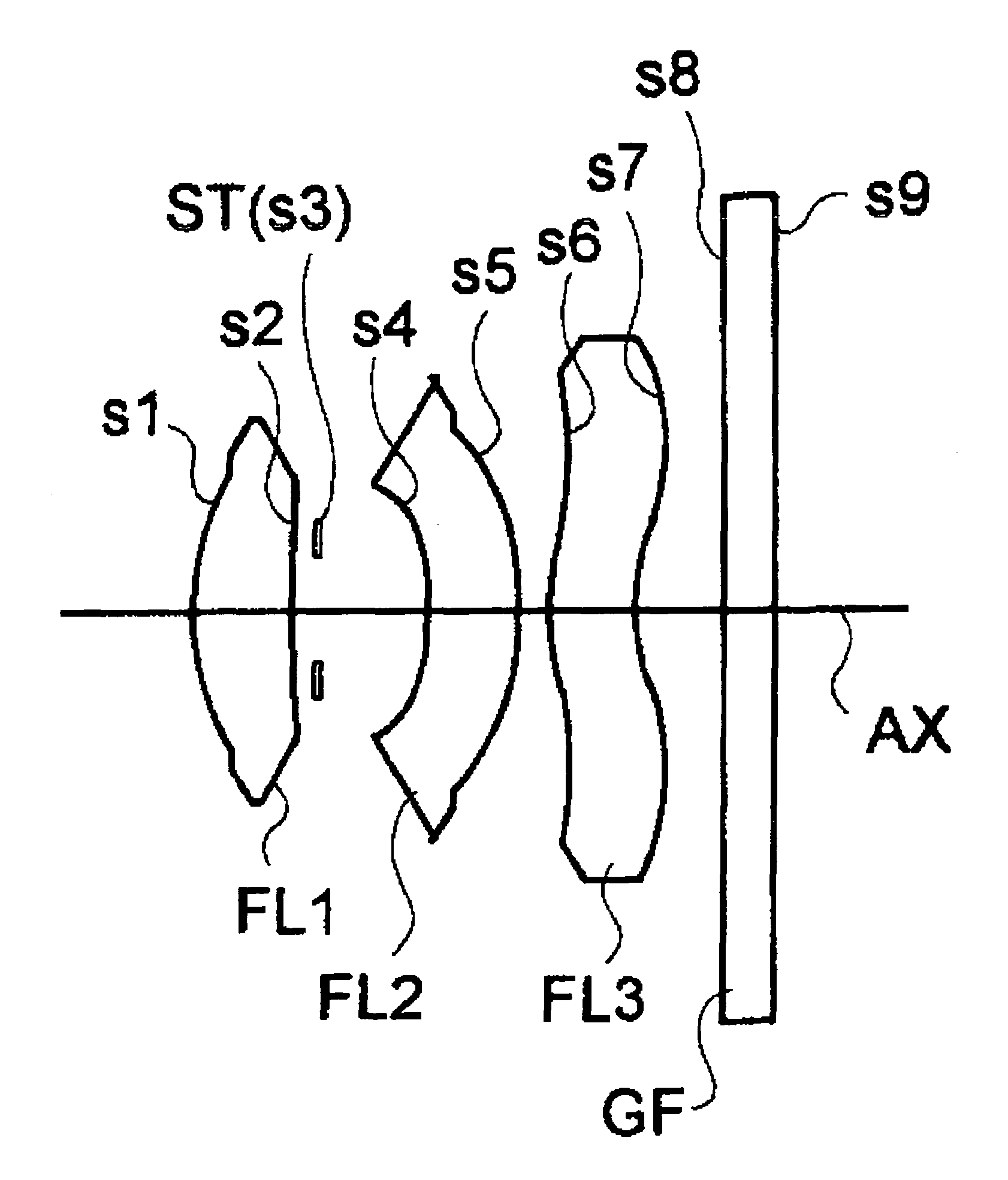
[0074]
f = 5.470, FNO = 4.0radius ofaxialrefractiveAbbecurvaturedistanceindexnumbers1 r1* = 2.611d1 = 1.021N1 = 1.67000ν1 = 57.07(FL1)s2 r2* = 8.247d2 = 0.261N2 = 1.53048ν2 = 55.72(FL2)s3 r3 = ∞(ST)d3 = 1.110N3 = 1.58340ν3 = 30.23(FL3)s4 r4* = −3.470d4 = 0.913N4 = 1.51680ν4 = 64.20(GF)s5 r5* = −4.569d5 = 0.307s6 r6* = 2.124d6 = 0.877s7 r7* = 1.708d7 = 0.900s8 r8 = ∞d8 = 0.500s9 r9 = ∞Σd = 5.889
[aspheric surface data of 1st surface (r1)][0075]ε=0.24691[0076]A2=0.0, A3=0.0, A4=−0.17737×10⁻², A5=0.0, A6=0.12774×10⁻², A7=0.0, A8=−0.28811×10⁻³, A9=0.0, A10=−0.28254×10⁻³, A11=0.0, A12=0.0, A13=0.0, A14=0.0, A15=0.0, A16=0.0
[aspheric surface data of 2nd surface (r2)][0077]ε=−12.575[0078]A2=0.0, A3=0.0, A4=−0.95444×10⁻², A5=0.0, A6=0.92656×10⁻³, A7=0.0, A8=0.55284×10⁻², A9=0.0, A10=−0.84266×10⁻², A11=0.0, A12=0.0, A13=0.0, A14=0.0, A15=0.0, A16=0.0
[aspheric surface data of 4th surface (r4)][0079]ε=0.0[0080]A2=0.0, A3=0.0, A4=0.21610×10⁻¹, A5=0.0, A6=−0.53855×10⁻¹, A7=0.0, A8=0.50367×10⁻², A9...
example 2
[0087]
f = 5.472, FNO = 4.0radius ofaxialrefractiveAbbecurvaturedistanceindexnumbers1 r1* = 2.632d1 = 1.008N1 = 1.67000ν1 = 57.07(FL1)s2 r2* = 8.093d2 = 0.261N2 = 1.53048ν2 = 55.72(FL2)s3 r3 = ∞(ST)d3 = 1.062N3 = 1.58340ν3 = 30.23(FL3)s4 r4* = −12.461d4 = 0.875N4 = 1.51680ν4 = 64.20(GF)s5 r5* = −218.181d5 = 0.349s6 r6* = 2.353d6 = 0.858s7 r7* = 1.986d7 = 0.900s8 r8 = ∞d8 = 0.500s9 r9 = ∞Σd = 5.813
[aspheric surface data of 1st surface (r1)][0088]ε=0.10945[0089]A2=0.0, A3=0.0, A4=−0.26963×10⁻², A5=0.0, A6=0.10004×10⁻², A7=0.0, A8=−0.27325×10⁻³, A9=0.0, A10=−0.39829×10⁻³, A11=0.0, A12=0.0, A13=0.0, A14=0.0, A15=0.0, A16=0.0
[aspheric surface data of 2nd surface (r2)][0090]ε=−14.000[0091]A2=0.0, A3=0.0, A4=−0.10487×10⁻¹, A5=0.0, A6=−0.83800×10⁻³, A7=0.0, A8=0.37339×10⁻², A9=0.0, A10=−0.58468×10⁻², A11=0.0, A12=0.0, A13=0.0, A14=0.0, A15=0.0, A16=0.0
[aspheric surface data of 4th surface (r4)][0092]A2=0.0, A3=0.0, A4=0.14339×10⁻¹, A5=0.0, A6=0.47853×10⁻¹, A7=0.0, A8=0.82075×10⁻², A9=0.0, A1...
PUM
 Abstract
Description
Claims
Application Information