Switching power supply circuit

a power supply circuit and power supply circuit technology, applied in the direction of electric variable regulation, process and machine control, instruments, etc., can solve the problems of inadequate implementation of zvs and abnormal operation in which zvs is not adequately implemented, and achieve the reduction of power loss, the effect of reducing the cost and size of the smoothing capacitor, and greatly improving the total power conversion efficiency characteristi

Inactive Publication Date: 2007-04-05
SONY CORP
View PDF5 Cites 25 Cited by
  • Summary
  • Abstract
  • Description
  • Claims
  • Application Information

AI Technical Summary

Benefits of technology

[0044] According to the embodiment of the present invention, abnormal operation in which zero voltage switching (ZVS) operation is not achieved in an intermediate load condition range is eliminated from a switching power supply circuit including a parallel resonant circuit on its primary side.
[0045] In addition, a ripple current close to a DC current is obtained as the current flowing into the switching converter from the smoothing capacitor in the rectifying and smoothing circuit that produces the rectified and smoothed voltage (DC input voltage) from an AC power supply. Therefore,

Problems solved by technology

This waveform indicates abnormal operation in which ZVS is not implemented adequately.
That is, it is known that a voltage resonant converter including a seconda

Method used


Image

  • Switching power supply circuit
  • Switching power supply circuit
  • Switching power supply circuit

Examples


first embodiment

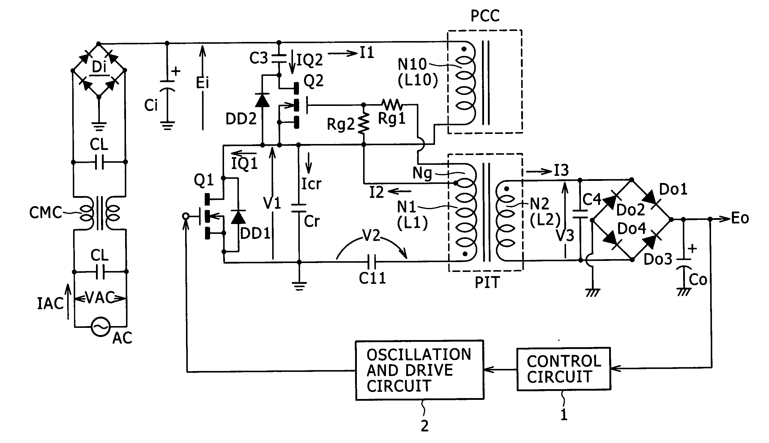
[0107] As one of the power supply circuits as the embodiments, a configuration example of the power supply circuit according to a first embodiment of the invention is shown in FIG. 4. The same parts in FIG. 4 as those in FIG. 3 are given the same numerals and the description therefor will be omitted.

[0108] In the power supply circuit shown in FIG. 4, a choke coil PCC (inductor L10) having a choke coil winding N10 is added to the primary side of a voltage resonant converter, so that class-E switching operation is achieved. The coupling coefficient between a primary winding N1 and a secondary winding N2 in an isolation converter transformer PIT is set to 0.8 or less, which corresponds to loose coupling. On the secondary side, a secondary-side partial voltage resonant capacitor C4 is connected in parallel to the secondary winding N2, so that a multiple resonant converter that obtains a DC output voltage from a full-wave bridge is constructed. Furthermore, a series circuit of a clamp c...

second embodiment

[0155]FIG. 12 illustrates a configuration example of the power supply circuit according to a second embodiment of the invention. The same parts in FIG. 12 as those in FIG. 4 are given the same numerals and the description therefor will be omitted.

[0156] In the power supply circuit shown in FIG. 12, a choke coil PCC (inductor L10) having a choke coil winding N10 is added to the primary side of a voltage resonant converter, so that class-E switching operation is achieved. The coupling coefficient between a primary winding N1 and a secondary winding N2 in an isolation converter transformer PIT is set to 0.8 or less, which corresponds to loose coupling. On the secondary side, a secondary-side series resonant capacitor C4 is connected in series to the secondary winding N2, so that a multiple resonant converter that obtains a DC output voltage from a full-wave bridge is constructed. Furthermore, a series circuit of a clamp capacitor C3 and an auxiliary switch element Q2 is connected in p...


PUM


Abstract

A switching power supply circuit includes a switching element, a converter transformer, a secondary-side rectifying and smoothing circuit, a switching element control unit, a choke coil, a primary-side series resonant circuit, a primary-side parallel resonant circuit, and a series circuit. The switching element implements switching for a direct-current (DC) voltage to convert the voltage into an alternating-current (AC) voltage. The choke coil is supplied with the voltage and is connected to one winding end of the primary winding and one terminal of the switching element. The primary-side series resonant circuit connects a primary-side series resonant capacitor, having a resonant frequency dominated by a leakage inductance. The primary-side parallel resonant circuit connects a primary-side parallel resonant capacitor in parallel to the switching element, having a resonant frequency. The series circuit is formed of a clamp capacitor and an auxiliary switch element which conducts in a non-conducting period of the switching element.

Description

CROSS REFERENCES TO RELATED APPLICATIONS [0001] The present invention contains subject matter related to Japanese Patent Application JP 2005-287759 filed with the Japanese Patent Office on Sep. 30, 2005 and Japanese Patent Application JP 2005-291082 filed with the Japanese Patent Office on Oct. 4, 2005, the entire contents of which being incorporated herein by reference. BACKGROUND OF THE INVENTION [0002] 1. Field of the Invention [0003] The present invention relates to a switching power supply circuit. [0004] 2. Description of the Related Art [0005] As types of a so-called soft switching power supply that employs a resonant converter, a current resonant type and a voltage resonant type have been widely known. Currently, half-bridge current resonant converters formed of a two-transistor switching element have been widely employed since they can easily be put into practical use. [0006] However, since characteristics of high-breakdown-voltage switching elements are currently being imp...

Claims


Application Information

Patent Timeline
IPC IPC(8): H02M3/335
CPCH02M1/34H02M3/33569H02M2001/342Y02B70/1433Y02B70/1491Y02B70/10H02M1/342H02M3/01H02M7/5388H02M7/48
Inventor YASUMURA, MASAYUKI
Owner SONY CORP
Why Eureka
Try Eureka