Direct-driven magnetic rotating apparatus

a magnetic rotating apparatus and direct drive technology, applied in the direction of positive displacement liquid engines, pumping machines, machines/engines, etc., can solve the problems of increasing the cost of components including the shaft increasing the cost of the entire apparatus, etc., to achieve the effect of increasing the torque transmission efficiency of the magnetic rotating apparatus, increasing the cost of the apparatus, and increasing the torqu

Active Publication Date: 2006-07-11
FOREST PINE ELECTRIC
View PDF15 Cites 20 Cited by
  • Summary
  • Abstract
  • Description
  • Claims
  • Application Information

AI Technical Summary

Benefits of technology

[0011]The present invention has been made in view of the above problems. Accordingly, it is an object of the present invention to provide a direct-driven magnetic rotating apparatus suitable for decreasing the cost and size of the apparatus in which the torque transmission efficiency of a magnetic rotating apparatus is increased remarkably to generate higher torque without increasing power consumption and upsizing the apparatus.
[0012]The present invention relates to a direct-driven magnetic rotating apparatus that rotates a rotational body using magnetic repulsive force. The foregoing object can be achieved by including a rotatable rotational shaft; a rotational body including a permanent magnet disposed radially outwards at a prescribed angle around the rim of the outer periphery and fixed to the rotational shaft; and an electromagnet disposed in the vicinity of the outer periphery rim of the rotational body so as to be periodically opposed to the permanent magnet in the vicinity thereof, wherein the permanent magnet is energized by the repulsive force of the electromagnet. The above object of the invention can be achieved more effectively by the permanent magnet including a plurality of permanent magnet plates. The above object can be achieved more effectively by the permanent magnet including a plurality of permanent magnet plates, wherein a permanent magnet plate having the largest magnetic force of the plurality of permanent magnet plates is arranged in the last position with respect to the rotating direction. The above object can be achieved more effectively by setting the numbers of the permanent magnets and the electromagnets plural and equal. The above object can be achieved more effectively by setting the number of the electromagnets two, and by joining ends of opposite polarities of the electromagnets together with a permeable body. The above object can be achieved more effectively by the rotational body including a propeller. The above object can be achieved more effectively by the rotational body including a drum of a washing machine or a dryer machine. The above object can be achieved more effectively by the rotational body including a wheel of an automobile.

Problems solved by technology

This produces the problem of decreasing the transmission efficiency of the torque because of the shaft and the problem of increasing the cost of components including the shaft and upsizing the entire apparatus.
Furthermore, in order to obtain larger torque or higher rotation speed, power consumption of the electromagnet will be increased or the number or size of permanent magnet plates must be increased to have stronger electromagnetic force, posing the problem of increasing cost and size of the apparatus.

Method used


Image

  • Direct-driven magnetic rotating apparatus
  • Direct-driven magnetic rotating apparatus
  • Direct-driven magnetic rotating apparatus

Examples


Embodiment Construction

[0023]Preferred Embodiments of the present invention will be specifically described hereinbelow with reference to the drawings.

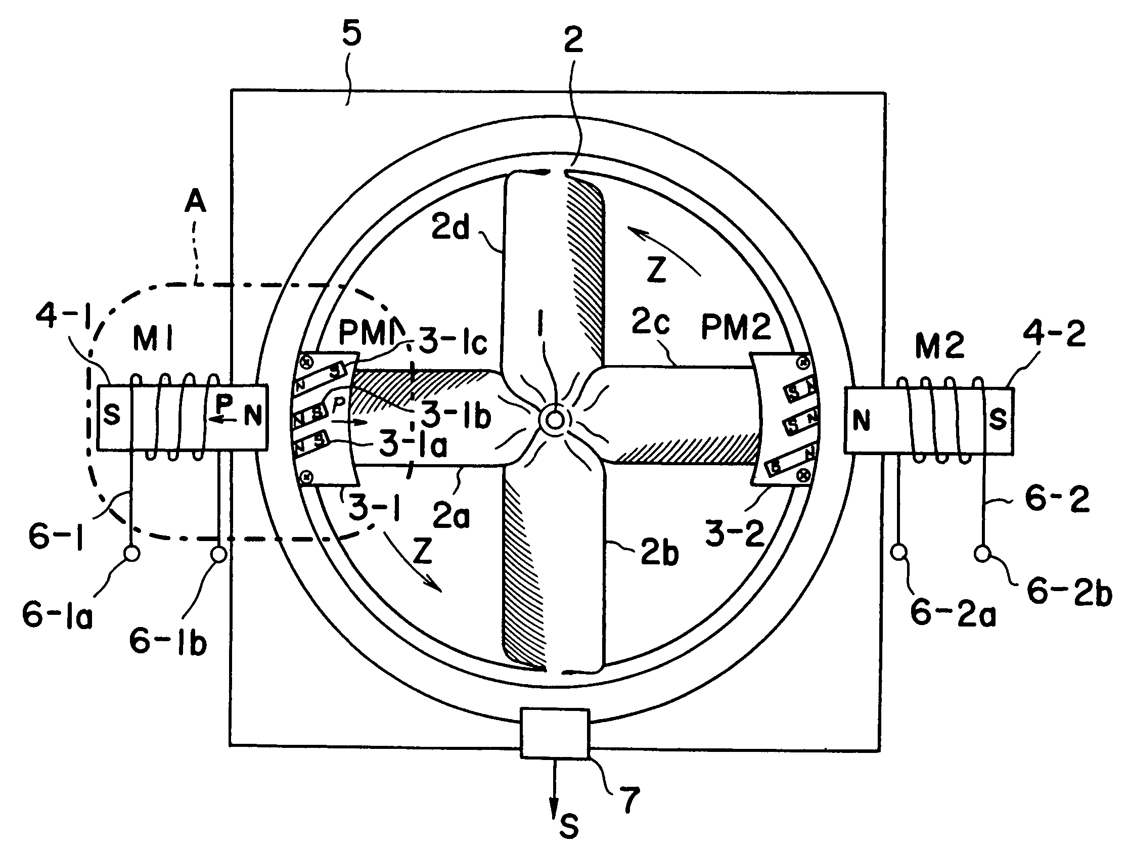
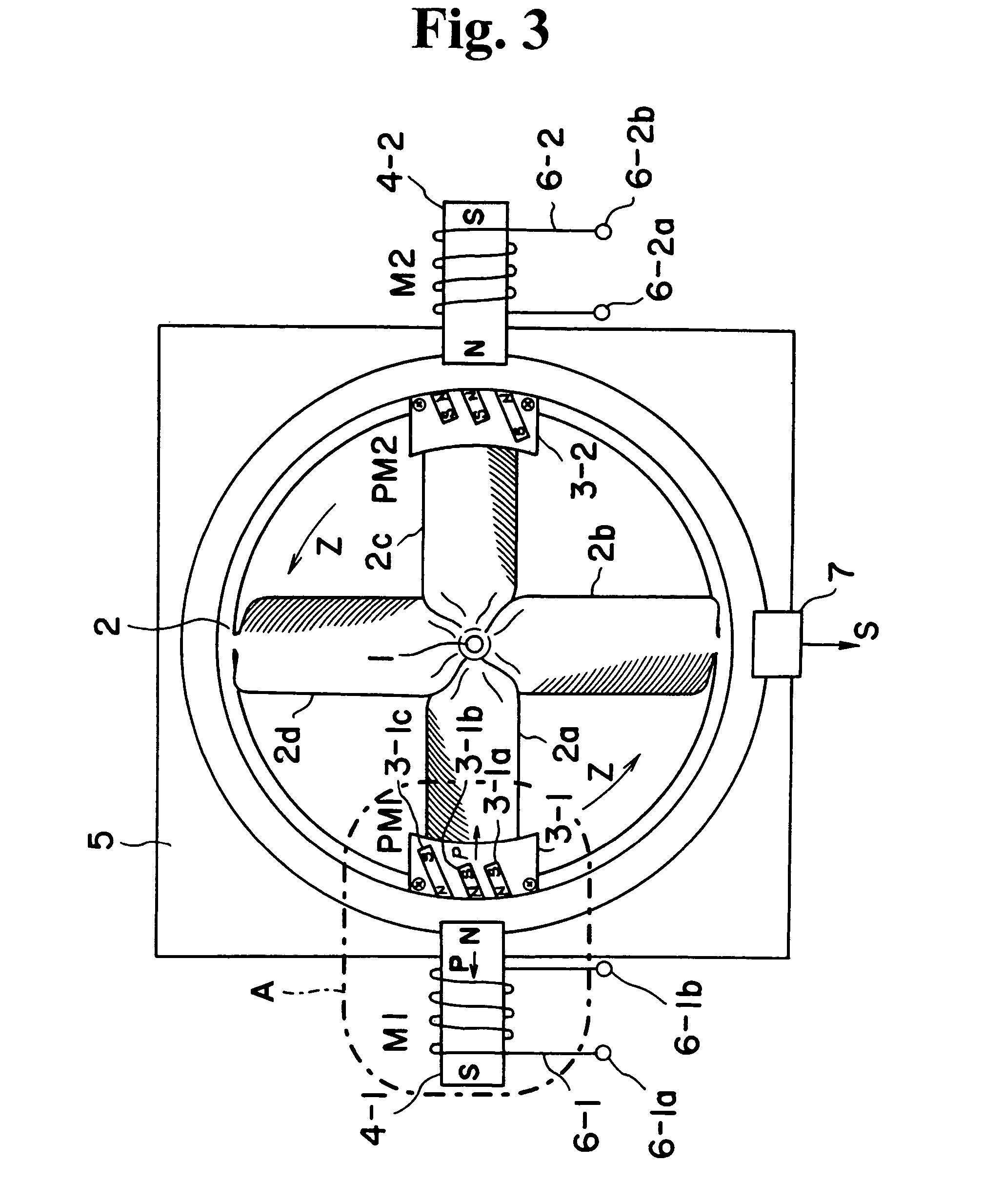
[0024]An embodiment in which a magnetic rotating apparatus according to an embodiment of the invention is applied to a fan or an air blower will first be described. FIG. 3 shows the structure of a fan incorporating the magnetic rotating apparatus. FIG. 4 shows an electromagnet control circuit for the electromagnet of the fan. FIG. 5 is an enlarged view of the part corresponding to part A of FIG. 3, illustrating the principle of high-torque generation of the magnetic rotating apparatus.

[0025]Referring to FIG. 3, a rotatable ring-shaped rotational body 2 is mounted to a rotational shaft 1 retained by a frame 5. The rotational body 2 includes a propeller. The propeller of this embodiment has four blades 2a, 2b, 2c, and 2d. At the rim of the outer periphery of the rotational body 2, permanent magnets 3-1 and 3-2 are mounted with an inclination of a prescribed an...


PUM


Abstract

Rotating-force transmission means is omitted by mounting permanent magnet plates directly to a rotational body which is rotated by magnetic repulsive force, thereby achieving a high-efficiency compact low-cost direct-driven magnetic rotating apparatus.

Description

BACKGROUND OF THE INVENTION[0001]1. Field of the Invention[0002]The present invention relates to a magnetic rotating apparatus for directly rotating a fan etc. and, more particularly, to a direct-driven magnetic rotating apparatus using the repulsive force between a permanent magnet and an electromagnet or a permanent magnet.[0003]2. Description of the Related Art[0004]It is known in the art to provide various rotating apparatuses using magnetic force and, particularly, permanent magnet motors are typical applications. Magnetic force has attractive force and repulsive force. Most of the application apparatuses use attractive force. However, it is more preferable to use repulsive force in force in view of efficiency and high-speed rotation. The inventor has therefore disclosed an application apparatus using repulsive force in Japanese Patent No. 2,968,918 (Patent Document 1) and JP-A-7-87725 (Patent Document 2).[0005]The invention disclosed in Patent Document 1 will now be described ...

Claims


Application Information

Patent Timeline
Patent Type & Authority Patents(United States)
IPC IPC(8): H02K9/00H02K9/06H02K21/12H02K41/03
CPCH02K41/03
Inventor MINATO, KOHEIMINATO, NOBUE
Owner FOREST PINE ELECTRIC
Why Eureka
Try Eureka