Whole-circle observation method for identifying fixed point of sonar imaging system

An imaging system and fixed-point technology, which is applied to the components of the TV system, image enhancement, image communication, etc., can solve the problems of small underwater area, poor imaging effect, low detection efficiency, etc., and achieve good application prospects and accuracy The effect of lifting and covering a large area

Inactive Publication Date: 2016-02-03
中船勘察设计研究院有限公司
View PDF9 Cites 5 Cited by
  • Summary
  • Abstract
  • Description
  • Claims
  • Application Information

AI Technical Summary

Problems solved by technology

[0002] At present, the identification sonar imaging system has obvious advantages in underwater imaging. The resolution of the instrument is very high, and it can obtain high-definition images in turbid water, especially when the instrument is in a static state. The imaging quality is very high. Poor imaging in motion
Traditional static shooting, fixed observation angle and fixed lens walking shooting, or handheld shooting by divers, it is difficult to achieve quantitative statistical analysis for multiple underwater
[0003] The single imaging range of the existing technology identification sonar imaging system is 29o in the horizontal direction and 14o in the vertical direction. In the case of a water depth of about 10m, the corresponding underwater area is small and the detection efficiency is low.

Method used


Image

  • Whole-circle observation method for identifying fixed point of sonar imaging system
  • Whole-circle observation method for identifying fixed point of sonar imaging system

Examples


Embodiment 1

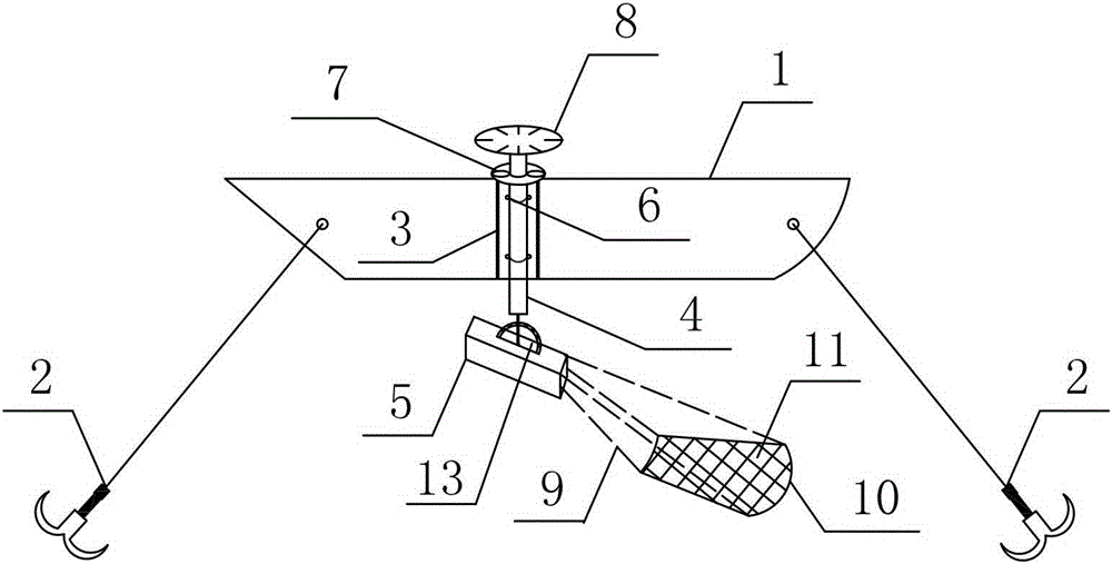
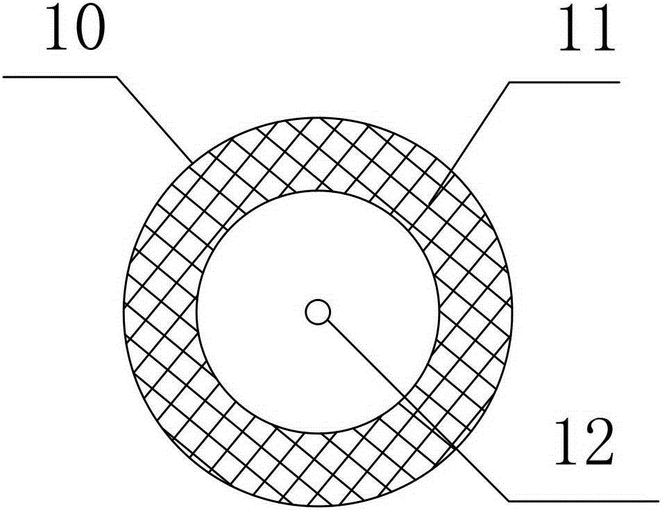
[0011] See attached figure 1 ~ attached figure 2 Firstly, the ship 1 is fixed with the anchor cable 2 and moored at the fixed point 12 of the underwater imaging area to be detected, so that the plane position of the ship 1 is basically fixed, and a section of channel steel 3 is welded to the side of the ship 1 with the notch facing outward And basically in a vertical state. The acoustic lens 5 for identifying the sonar imaging system is set on the fixed plate 13 at the bottom of the rotating rod 4, and the rotating rod 4 is set on the top of the channel steel 3 by the upper flange 7, and two "U"-shaped bolts 6 are used to secure the The rotating rod 4 is fixed on the channel steel 3. The entire imaging system is set up on the flange 7 on the upper part of the rotating rod 4, and the flange 7 is provided with a circular angle plate 8. After the installation of the entire system, the observation angle of the acoustic lens 5 is adjusted to make the detected target clearly imag...


PUM


Abstract

The invention discloses a whole-circle observation method for identifying a fixed point of a sonar imaging system. The whole-circle observation method for identifying the fixed point of the sonar imaging system is characterized by comprising the steps of arranging an acoustic lens on a rotary rod; relative to a water surface, vertically inserting the rotary rod to a side surface of a ship which is anchored and fixed in an imaging to-be-detected area; rotating the rotary rod for an angle of 20 degrees at each time so as to perform 360-degree whole-circle observation and camera shooting for an underwater target; splicing all the images into a complete underwater target image map; then identifying and interpreting the image map; calculating a specific surface area and a number of detected targets within an imaging range; and finishing quantified analysis of detection of the underwater targets. In comparison with the prior art, the whole-circle observation method for identifying the fixed point of the sonar imaging system achieves 360-degree whole-circle observation and continuous camera shooting, a generated photo covers a big area, and the working efficiency is 15 times that of single imaging; and the specific surface area and the number of the detected targets within the imaging range are calculated through a sight distance and the number of the detected targets in the image, so that quantified statistic analysis of underwater detection is realized, and the accuracy is greatly improved.

Description

technical field [0001] The invention relates to the technical field of underwater target imaging and quantitative detection, in particular to a full-circle observation method for identifying fixed points of a sonar imaging system. Background technique [0002] At present, the identification sonar imaging system has obvious advantages in underwater imaging. The resolution of the instrument is very high, and it can obtain high-definition images in turbid water, especially when the instrument is in a static state. The imaging quality is very high. The imaging effect in the motion state is poor. Traditional static shooting, fixed observation angle and fixed lens walking shooting, or handheld shooting by divers, it is difficult to achieve quantitative statistical analysis for multiple underwater. [0003] The single imaging range of the prior art identification sonar imaging system is 29o in the horizontal direction and 14o in the vertical direction. In the case of a water depth...

Claims


Application Information

Patent Timeline
Patent Type & Authority Applications(China)
IPC IPC(8): H04N5/232G06T3/40G06T5/50
Inventor 孙丰樊永杰张小荣欧阳杰
Owner 中船勘察设计研究院有限公司
Why Eureka
Try Eureka