Unlock instant, AI-driven research and patent intelligence for your innovation.
Heat management and energy recycling system and method for battery module group of electric vehicle
What is Al technical title?
Al technical title is built by PatSnap Al team. It summarizes the technical point description of the patent document.
A battery module and energy recovery technology, applied in secondary batteries, circuits, electrical components, etc., can solve the problems of no energy recovery, difficult control, low reliability, etc., to increase usage, increase coverage area, improve safety effect
Active Publication Date: 2019-07-02
SHANDONG UNIV
View PDF5 Cites 20 Cited by
Summary
Abstract
Description
Claims
Application Information
AI Technical Summary
This helps you quickly interpret patents by identifying the three key elements:
Problems solved by technology
Method used
Benefits of technology
Problems solved by technology
However, this technology is only suitable for cylindrical batteries; at the same time, the structure is relatively complex, the control of forward connection and reverse connection operation is difficult, and the reliability is low; this technology does not have the function of energy recovery
Method used
Image
Click on the blue label to locate the original text in one second.
Reading with bidirectional positioning of images and text.
Examples
Embodiment 1
[0054] Such as Figure 1-13 As described above, the present disclosure provides a thermal management and energy recovery system for an electric vehicle battery module;
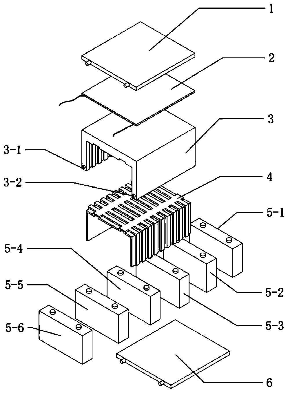
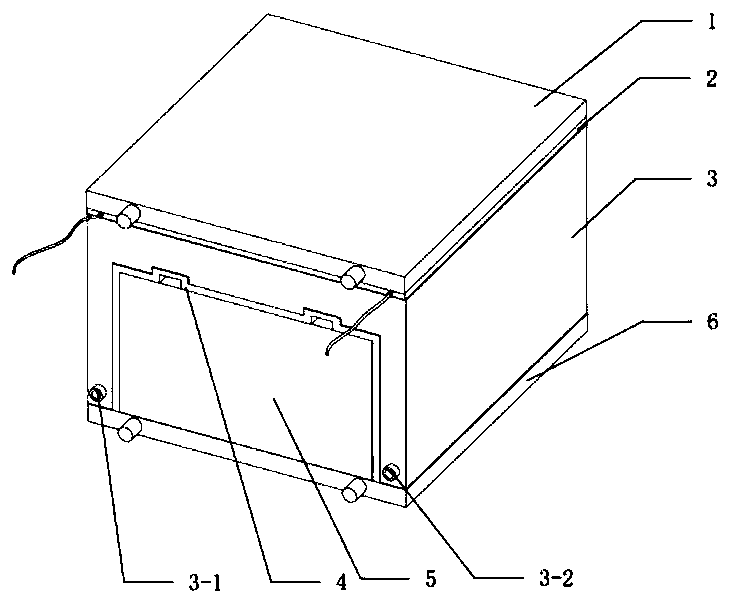
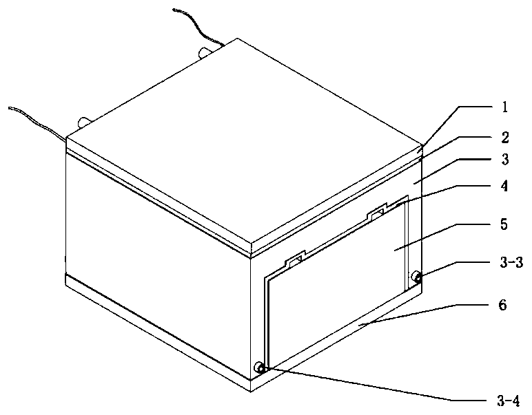
[0055] Such as figure 1 , figure 2 , image 3 , Figure 12 with Figure 13 As shown, the present disclosure is installed together with the battery module 5 of the electric vehicle and connected with the electronic control unit ECU10 of the electric vehicle, and its technical solution includes a thermoelectric power generation module, a cooling and heating module and an electronic control module.
[0056] Such as figure 1 , figure 2 , image 3 , Figure 4 , Figure 5 , Image 6 , Figure 7 , Figure 8 , Figure 9 As shown, the thermoelectric power generation module includes a first liquid cold plate 1 , a thermoelectric power generation sheet 2 , a phase change material box 3 , a battery module case 4 and a second liquid cold plate 6 .
[0057] Such as figure 1 , Figure 5 , Figure 10 , Fi...
Embodiment 2
[0080] Such as Figure 14 As shown, Embodiment 2 of the present disclosure provides a method for thermal management and energy recovery of an electric vehicle battery module, and the steps are as follows:
[0081] Set the first temperature threshold T according to the phase changemelting point of the phase change material 1 , the temperature T of the phase change material is collected in real time and compared with the first temperature threshold T 1 comparing;
[0082] When the temperature of the phase change material rises to the first temperature threshold T 1 When , the phase change material begins to change phase, absorbs the heat of the battery module and stores the heat, and maintains the temperature of the battery module at the first temperature threshold T 1 nearby;
[0083] When the phase change material in the phase change material box is completely melted, the temperature of the battery module and the phase change material starts to rise further, which is grea...
PUM
Abstract
The invention provides a heat management and energy recyclingsystem and method for a battery module group of an electric vehicle. The system comprises a thermoelectric power generation module, a cooling and heating module and an electronic control module, wherein the thermoelectric power generation module is connected with the battery module; the battery module is used for recycling heat emittedby the battery module and supplying power to the outside. The cooling and heating module is connected with the thermoelectric power generation module, is used for providing cooling liquid for the thermoelectric power generation module to produce temperature difference, and is also used for achieving the cooling or temperature heating of the battery module. The electronic control module is connected with the thermoelectric power generation module and the cooling and heating module, and is used for achieving dynamic control over temperature difference power generation and cooling and heating. When the temperature of the battery module is high, too high, low and too low, the electronic control module is used for achieving control over the temperature difference power generation module and thecooling and heating module, and the high-temperature heat dissipation capacity and the low-temperature heat preservation capacity of the battery module are greatly improved.
Description
technical field [0001] The present disclosure relates to the technical field of electric vehicle battery heat management, and in particular to a system and method for heat management and energy recovery of electric vehicle battery modules. Background technique [0002] The statements in this section merely provide background information related to the present disclosure and may not necessarily constitute prior art. [0003] Today, when the energy crisis is becoming increasingly prominent and environmental protection issues are receiving more and more attention, new energy vehicles, especially electric vehicles, have developed rapidly because they do not use chemical fuels, have no emissions, and have no pollution. In this type of car, battery cells are usually connected in series and parallel to form a battery module, and several battery modules are then connected in series and parallel to form a battery pack to provide suitable voltage and sufficient power. However, on the...
Claims
Application Information
Patent Timeline
Application Date:The date an application was filed.
Publication Date:The date a patent or application was officially published.
First Publication Date:The earliest publication date of a patent with the same application number.
Issue Date:Publication date of the patent grant document.
PCT Entry Date:The Entry date of PCT National Phase.
Estimated Expiry Date:The statutory expiry date of a patent right according to the Patent Law, and it is the longest term of protection that the patent right can achieve without the termination of the patent right due to other reasons(Term extension factor has been taken into account ).
Invalid Date:Actual expiry date is based on effective date or publication date of legal transaction data of invalid patent.

