Eureka AIR delivers breakthrough ideas for toughest innovation challenges, trusted by R&D personnel around the world.

Horizontal pneumatic tube pressing machine

A tube crimping machine, horizontal technology, applied in the field of wire harness, can solve the problems of undiscovered patent documents, easy to cause industrial accidents, difficult to guarantee quality, etc., and achieve the effect of saving manpower, simple structure and fast crimping speed

Inactive Publication Date: 2016-02-10
天津五洲元通实业股份有限公司
View PDF0 Cites 0 Cited by
  • Summary
  • Abstract
  • Description
  • Claims
  • Application Information

AI Technical Summary

Problems solved by technology

At present, the installation of the wire harness iron protection tube is generally done manually, that is, the wire harness is put into the iron protection tube, and the space between the iron protection tube and the wire harness is kept, and the rubber hammer is used to smash it. Not only is it very laborious, but the quality is difficult to guarantee. Production The efficiency is very low, and it is also prone to industrial accidents
[0003] Through searching, no published patent documents identical to this patent application were found

Method used


Image

  • Horizontal pneumatic tube pressing machine
  • Horizontal pneumatic tube pressing machine
  • Horizontal pneumatic tube pressing machine

Examples


Embodiment Construction

[0014] The present invention will be further described in detail below in conjunction with the accompanying drawings and through specific embodiments. The following embodiments are only descriptive, not restrictive, and cannot limit the protection scope of the present invention.

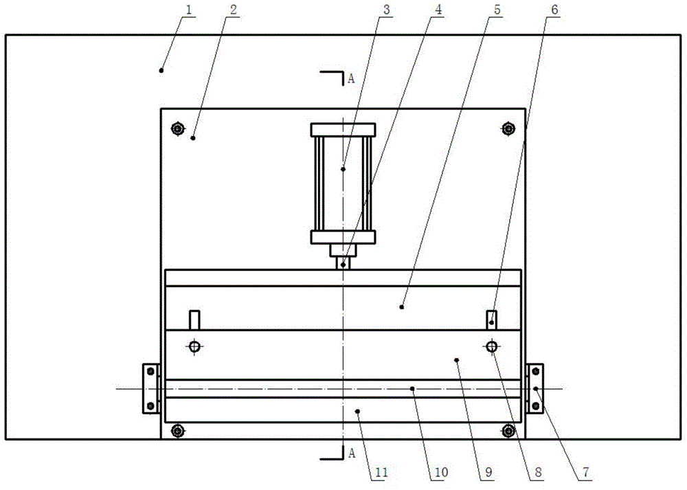
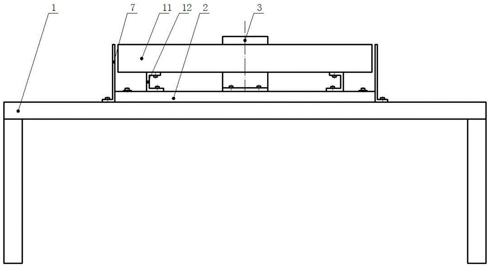
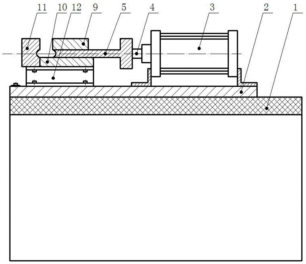
[0015] A horizontal pneumatic tube crimping machine, comprising a workbench 1, a base 2, a cylinder 3, a movable mold 5, a static mold 11, a guide table 10, and an upper press table 9, the base is fixed horizontally on the workbench, and the base is fixed on the base The middle and rear part of the seat is a horizontal fixed cylinder, the front end of the plunger 4 of the cylinder is fixed with the movable mold, and the static mold is fixed on the base corresponding to the front of the movable mold, and the static mold is fixed on the support frame 12 , the support frame is fixed on the base, and a guide table is fixed between the movable mold and the support frame. There are mold cavities (without l...


PUM


Abstract

The invention relates to a horizontal pneumatic tube pressing machine. The horizontal pneumatic tube pressing machine comprises a workbench, a base, a cylinder, a movable die and a fixed die; the base is horizontally and fixedly installed on the workbench, the cylinder is horizontally and fixedly installed on the middle rear portion of the base, the movable die is fixedly installed at the front end of a plunger piston of the cylinder, the fixed die is fixedly installed on the portion, corresponding to the front portion of the movable die and opposite to the movable die, of the base, and the fixed die is fixedly installed on support frames which are fixed on the base; a guide table is fixedly installed between the movable and the support frames, the opposite faces of the movable die and the fixed die are each provided with a die cavity, the two sides of the upper plane of the movable are each provided with a long-strip guide hole, a guide column is fixedly installed on the portions, corresponding to the guide holes, of the guide table, the upper ends of the two guide columns are both fixedly connected with an upper pressing table, and the upper pressing table is fixedly installed above the movable die through the guide columns. According to the tube pressing machine, a driving rod mode is adopted, a pneumatic pump is used for serving as power, and by means of the dies, an iron protection tube can be perfectly connected to a wire harness in a pressed mode; the pressing connection speed is high, the production efficiency is high, manpower is saved, and the personal safety is guaranteed.

Description

technical field [0001] The invention belongs to the field of wire harnesses, and relates to iron protective tubes for wire harnesses, in particular to a horizontal pneumatic tube crimping machine. Background technique [0002] At present, the main part of the engine wiring harness used in motor vehicles such as agricultural machinery and construction machinery needs to be protected by iron protective tubes to avoid the hidden danger of wire harness wear and fire. At present, the installation of the wire harness iron protection tube is generally done manually, that is, the wire harness is put into the iron protection tube, and the space between the iron protection tube and the wire harness is maintained, and the rubber hammer is used to smash it. Not only is it very laborious, but the quality is difficult to guarantee. Production The efficiency is very low, and it is also prone to industrial accidents. [0003] By searching, no published patent documents identical with this ...

Claims


Application Information

Patent Timeline
IPC IPC(8): B23P19/027
Inventor 江万山
Owner 天津五洲元通实业股份有限公司
Why Eureka
Eureka Blog
Learn More