led

A technology of light-emitting diodes and light-emitting structures, which is applied in the direction of semiconductor devices, electrical components, circuits, etc., to prevent bowing, prevent diffusion, and improve current expansion performance.

Active Publication Date: 2018-12-28
SEOUL VIOSYS CO LTD
View PDF7 Cites 0 Cited by
  • Summary
  • Abstract
  • Description
  • Claims
  • Application Information

AI Technical Summary

Problems solved by technology

Since the spacer directly adjoins the solder paste in the LED module, metal elements in the solder paste, such as tin (Sn), diffuse into the LED through the spacer and can create a short circuit in the LED, thereby causing device failure

Method used


Image

  • led
  • led
  • led

Examples


Embodiment Construction

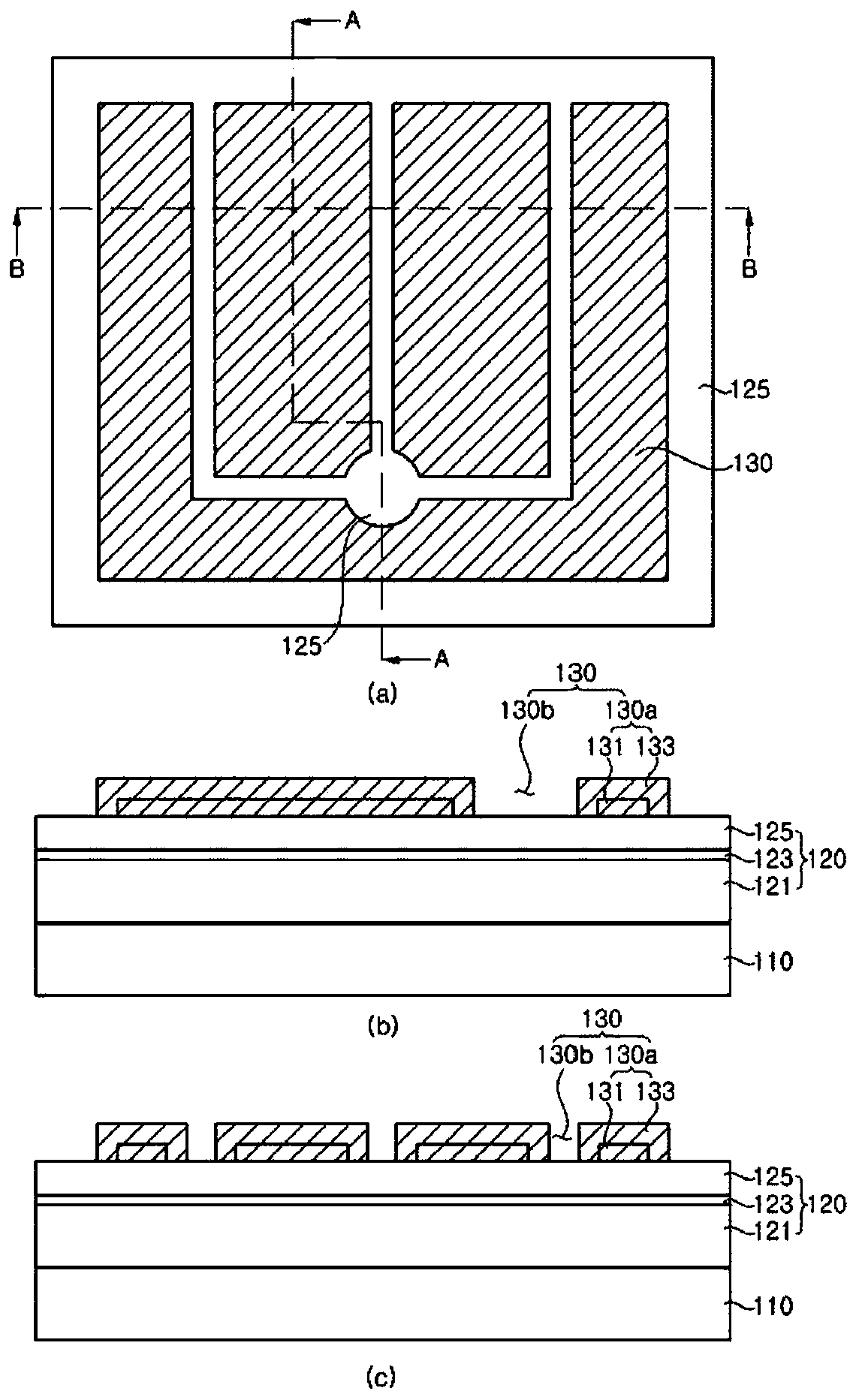
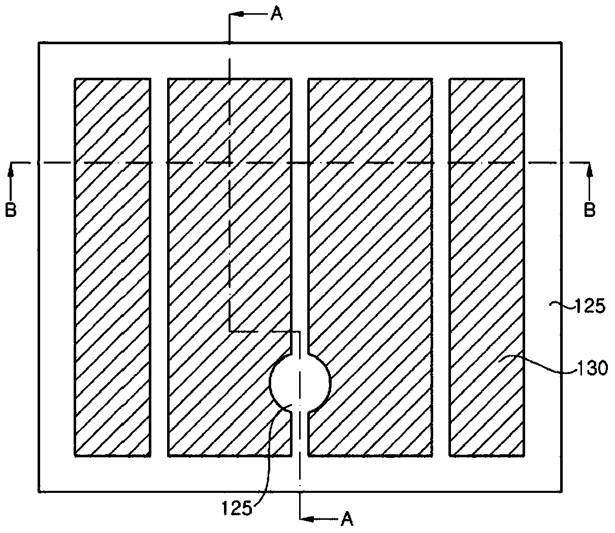
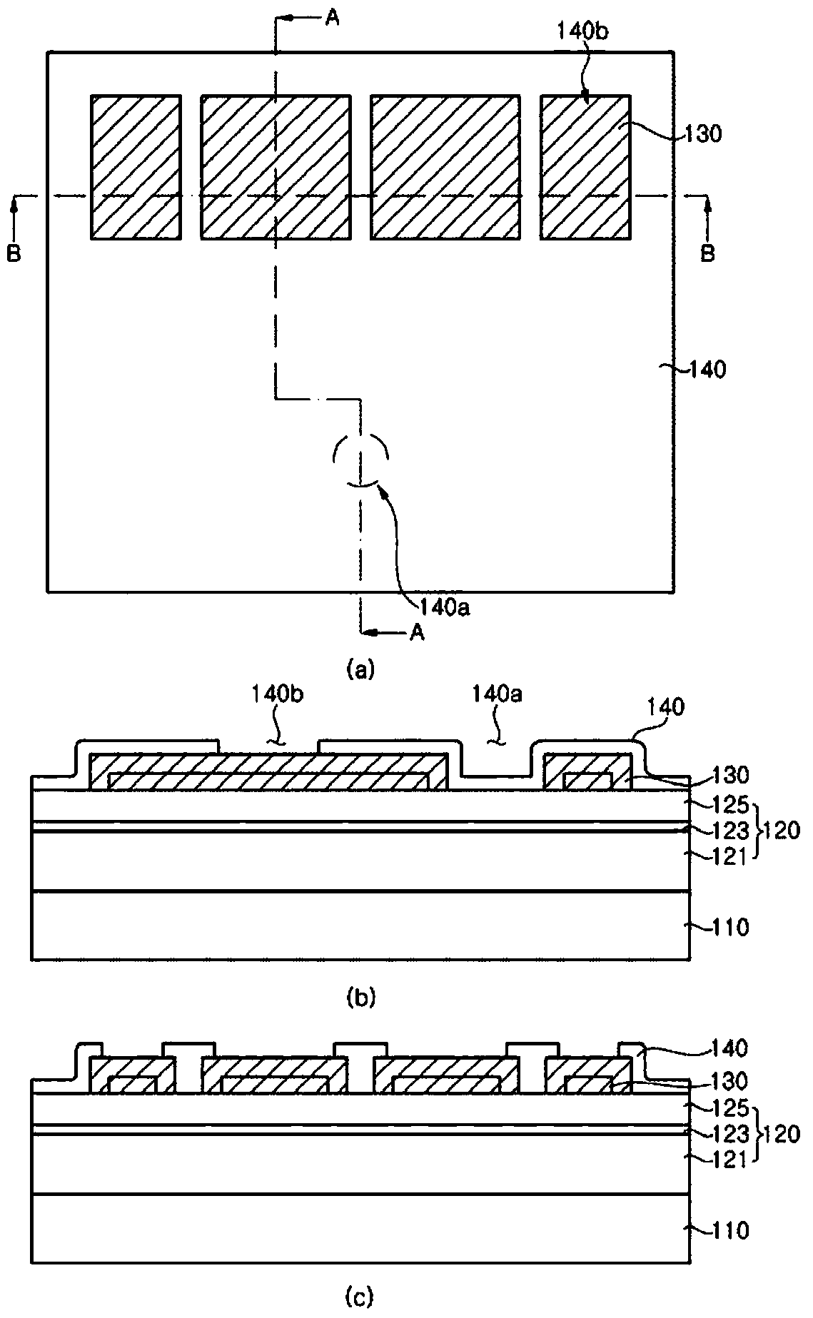
[0087] Exemplary embodiments of the present invention will be described in detail below with reference to the accompanying drawings. The following embodiments are provided by way of examples so as to fully convey the spirit of the present invention to those skilled in the art to which the present invention pertains. Therefore, the present invention is not limited to the embodiments disclosed herein and may also be implemented in different forms. In the drawings, the width, length, thickness and the like of elements may be exaggerated for clarity and descriptive purposes. When an element or layer is referred to as being "on" or "on" another element or layer, it can be directly on or "on" the other element or layer, or intervening elements or layers may be present. . In this specification, the same reference numerals refer to the same elements having the same or similar functions throughout.

[0088] Figure 1a to Figure 6d are plan and cross-sectional views illustrating a l...


PUM


Abstract

Exemplary embodiments provide a light emitting diode that includes: at least one lower electrode providing a passage for electric current; a light emitting structure placed over the at least one lower electrode to be electrically connected to the lower electrode, the light emitting structure is disposed to form at least one via-hole; a reflective electrode layer placed between the at least one lower electrode and the light emitting structure; and an electrode pattern formed around the light emitting structure and electrically connecting the lower electrode to the light emitting structure through the via-hole.

Description

[0001] Cross References to Related Applications [0002] This application claims priority and benefit from Korean Patent Application No. 10-2014-0072356 filed on June 13, 2014 and Korean Patent Application No. 10-2014-0081058 filed on June 30, 2014, which were filed on All purposes are incorporated herein by reference as if reproduced in full. technical field [0003] Exemplary embodiments of the present invention relate to a light emitting diode and a method of manufacturing the light emitting diode. More particularly, exemplary embodiments of the present invention relate to a light emitting diode manufactured by separating a growth substrate at a wafer level and a method of manufacturing the light emitting diode. Background technique [0004] A light emitting diode refers to an inorganic semiconductor device that emits light generated by recombination of electrons and holes and is used in various fields such as displays, car lights, general lighting, and the like. [00...

Claims


Application Information

Patent Timeline
Patent Type & Authority Patents(China)
IPC IPC(8): H01L33/38H01L33/40H01L33/00
CPCH01L33/0093H01L33/38H01L33/385H01L33/405H01L33/20H01L33/382H01L33/42H01L33/46H01L33/54H01L33/56
Inventor 蔡钟炫
Owner SEOUL VIOSYS CO LTD
Why Eureka
Try Eureka