Intelligent glasses and control method for controlling unmanned aerial vehicle

A technology of smart glasses and drones, applied in the input/output of user/computer interaction, three-dimensional position/channel control, computer components, etc., which can solve the difficult immersive feeling, reduce the experience effect, and image Content can only be obtained from third-party screens, etc., to achieve the effects of easy portability, high framing authenticity, and good control effects

Active Publication Date: 2016-02-17
杨珊珊
View PDF7 Cites 62 Cited by
  • Summary
  • Abstract
  • Description
  • Claims
  • Application Information

AI Technical Summary

Problems solved by technology

[0003] In order to facilitate the remote control of drones, at present, the surrounding images are transmitted to the display screen of the corresponding controller in real time through the camera in front of the drone, and the operator then takes a view or performs corresponding control according to the pattern situation. However, this observation One defect of the method is: the image content can only be obtained from the third-party screen, it is difficult to give people an immersive feeling
In this way, the wearer of the head-mounted smart glasses has no control over what he wants to observe, and can only passively wait for the change of the observation range, which will greatly reduce the experience effect

Method used


Image

  • Intelligent glasses and control method for controlling unmanned aerial vehicle
  • Intelligent glasses and control method for controlling unmanned aerial vehicle
  • Intelligent glasses and control method for controlling unmanned aerial vehicle

Examples


Embodiment 1

[0049] Embodiment 1. A smart glasses for controlling drones.

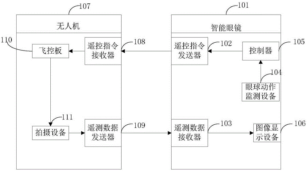
[0050] figure 1 This is a schematic diagram of the structure of smart glasses for controlling drones in the first embodiment of the present invention. The embodiment of the present invention will combine figure 1 Give specific instructions.

[0051] Such as figure 1 As shown, the embodiment of the present invention provides a smart glasses 101 for controlling a drone 107. The drone 107 includes a flight control board 110, a shooting device 111 for aerial photography, a remote control command receiver 108, and a telemetry A data transmitter 109, the flight control board 110 is electrically connected to the remote control instruction receiver 108, the photographing device 111 is electrically connected to the telemetry data transmitter 109, and the smart glasses 101 includes a remote control instruction transmitter 102, A telemetry data receiver 103, an image display device 106, an eye movement monitoring device 104, a con...

Embodiment 2

[0097] The second embodiment is a smart glasses for controlling drones.

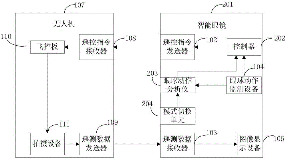
[0098] figure 2 It is a schematic diagram of the structure of smart glasses for controlling drones in the second embodiment of the present invention. The embodiment of the present invention will combine figure 2 Give specific instructions.

[0099] Such as figure 2 As shown, the embodiment of the present invention provides a smart glasses 201 for controlling a drone 107. The drone 107 includes a flight control board 110 and a shooting device 111 for aerial photography, a remote control command receiver 108, and a telemetry A data transmitter 109, the flight control board 110 is electrically connected to the remote control instruction receiver 108, the photographing device 111 is electrically connected to the telemetry data transmitter 109, and the smart glasses 201 includes a remote control instruction transmitter 102, A telemetry data receiver 103, an image display device 106, an eye movement monitoring d...

Embodiment 3

[0127] The third embodiment is a method for using smart glasses to control a drone.

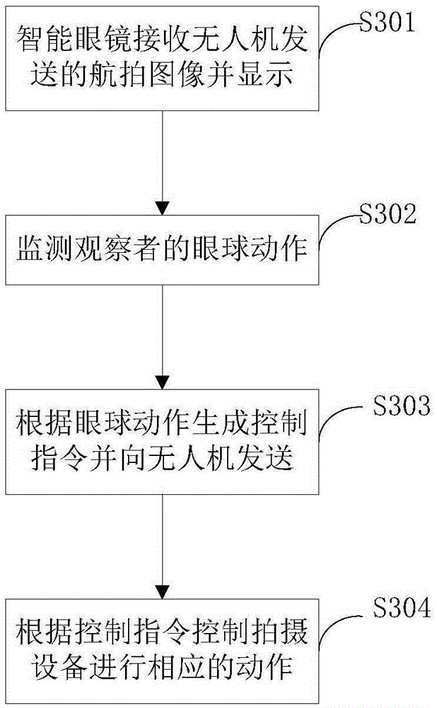
[0128] image 3 This is a flowchart of a method for controlling a drone with smart glasses in the third embodiment of the present invention, and the embodiment of the present invention will combine image 3 Give specific instructions.

[0129] Such as image 3 As shown, the embodiment of the present invention provides a method for using smart glasses to control a drone. The method includes the following steps:

[0130] Step S301: The smart glasses receive and display the aerial image sent by the drone;

[0131] Step S302: monitoring the user's eye movements;

[0132] Step S303: Generate a control instruction according to the eye movement and send it to the drone;

[0133] Step S304: Control the photographing device to perform corresponding actions according to the control instruction.

[0134] Preferably, in the embodiment of the present invention, the control instructions include pan / tilt control instru...


PUM


Abstract

The invention discloses a pair of intelligent glasses and a control method for controlling an unmanned aerial vehicle, and belongs to the field of unmanned aerial vehicle application. The pair of intelligent glasses comprises a remote control command sender, a telemetry data receiver, an image display device, an eyeball motion monitoring device and a controller, wherein the eyeball motion monitoring device is arranged on the image display device and is used for transmitting aerial images of a shooting device carried on the unmanned aerial vehicle to the image display device for displaying; the controller is electrically connected with the eyeball motion monitoring device and the remote control command sender respectively, and is applicable to generating a control command and transmitting the control command to the unmanned aerial vehicle according to user eyeball motions detected by the eyeball motion monitoring device; and the shooting device is controlled according to the control command to perform corresponding actions. The invention provides a conception of adjusting the direction of the shooting device carried on the unmanned aerial vehicle by using the eyeball motions, and the natural motions of eyeballs during observation are fully utilized to automatically adjust the best field of view. Meanwhile, the eyeball motions are combined with the flight path control of the unmanned aerial vehicle.

Description

Technical field [0001] The invention relates to the technical field of UAV application, in particular to a smart glasses for controlling UAV and a control method. Background technique [0002] With the development of drones, especially multi-rotor unmanned aerial vehicle technology, the use of multi-rotor unmanned aerial vehicle aerial photography, and through real-time image transmission technology, the aerial image is transmitted back to the user's client, so that the user can real-time Sharing vision with drones has become a promising demand. In this case, the drone is like a flying telescope, and the user can observe the distant scene through the screen. [0003] In order to facilitate the remote control of the drone, currently the surrounding image is mainly transmitted to the display screen of the corresponding controller through the camera in front of the drone in real time. The operator then takes the view according to the pattern or performs corresponding control. However...

Claims


Application Information

Patent Timeline
Patent Type & Authority Applications(China)
IPC IPC(8): G05D1/10H04N7/18G06F3/01G02B27/01
Inventor 杨珊珊
Owner 杨珊珊
Why Eureka
Try Eureka