Supercharge Your Innovation With Domain-Expert AI Agents!

Fluidization unit and discharge system

一种流化、排放管的技术,应用在化学仪器和方法、运输和包装、分离方法等方向,能够解决低效率等问题

Active Publication Date: 2017-09-19
FMC SEPARATION SYST BV
View PDF1 Cites 0 Cited by
  • Summary
  • Abstract
  • Description
  • Claims
  • Application Information

AI Technical Summary

Problems solved by technology

A disadvantage of the disclosed unit is a limited range of operation and thus a rather low efficiency for sand removal

Method used


Image

  • Fluidization unit and discharge system
  • Fluidization unit and discharge system
  • Fluidization unit and discharge system

Examples


Embodiment Construction

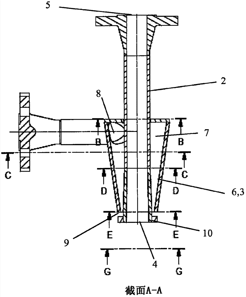
[0027] figure 1 An embodiment of a fluidization unit according to the invention is shown. The unit is designed to be incorporated into a vessel desanding system for removal of accumulated solids / sand. The unit can be operated in on-line desanding mode, or in batch desandering operation during routine maintenance. The unit includes a discharge pipe 2 for removal of fluidized solids. The suspension including fluidized solids is sucked into discharge inlet 4 and removed through discharge outlet 5 . Solids are fluidized by the use of pressurized liquids, usually water. This liquid is introduced into the supply conduit 3 through the inlet 8 . The supply conduit 3 comprises a casing 6 arranged around the discharge pipe 2 . The inner surface of the casing and the outer surface of the discharge pipe provide an annular space 7 between them. see Figure 6 and 7 , in a plane substantially perpendicular to the centerline of the discharge pipe, the cross-section of the annular spac...


PUM


Abstract

The present invention provides a fluidization unit (1) for use in a vessel desander system, comprising a discharge pipe (2) and a supply pipe (3), the discharge pipe comprising a discharge inlet (4) and a discharge outlet (5) , and the supply duct is formed by a housing (6) arranged around the discharge duct so as to define an annular space (7) between the outer surface of said duct and the inner surface of the housing, the supply duct comprising pressurized A liquid inlet (8) and a pressurized liquid outlet (9), wherein the pressurized liquid outlet during use provides a flow of pressurized liquid having a generally elliptical cross-section.

Description

technical field [0001] The present invention relates to a fluidization unit for use in a vessel desander system and a vessel desander system comprising said unit. Background technique [0002] Solids generation is a common phenomenon in the petroleum industry. Sand or other solid particles often accompany oil, gas and water from reservoirs to surface production facilities. This will cause several operational problems such as erosion of upstream equipment, blockage of flow lines and buildup in production vessels. The main consequences of these problems can be reduced performance of separator internals and unplanned shutdown of the entire production operation. To avoid such problems, container desanding systems are often used. Buildup of solids occurs in all such systems. To remove solids from a grit removal system, the accumulated solids are fluidized and drained from the system through the use of a liquid, usually water. There are many different methods for fluidizing / d...

Claims


Application Information

Patent Timeline
Patent Type & Authority Patents(China)
IPC IPC(8): B01D21/24B65G53/16B65D88/72B65G53/30
CPCB01D21/2472B01D21/24
Inventor 塔里格·穆克塔尔·阿布达拉阿德昆莱·奥卢塔约·奥帕瓦莱
Owner FMC SEPARATION SYST BV
Features
  • R&D
  • Intellectual Property
  • Life Sciences
  • Materials
  • Tech Scout
  • Unparalleled Data Quality
  • Higher Quality Content
  • 60% Fewer Hallucinations
Learn More