Supercharge Your Innovation With Domain-Expert AI Agents!

Unmanned-plane horizontal-speed control method based on fusion of data of acceleration sensor and optical-flow sensor

An acceleration sensor and optical flow sensor technology, which is applied in the field of autonomous positioning of unmanned aerial vehicles based on data fusion of acceleration sensors and optical flow sensors, to achieve the effect of stable autonomous hovering

Inactive Publication Date: 2016-02-24
TIANJIN UNIV
View PDF5 Cites 22 Cited by
  • Summary
  • Abstract
  • Description
  • Claims
  • Application Information

AI Technical Summary

Problems solved by technology

[0005] Researchers from the Swiss Federal Institute of Technology in Zurich used the PX4FLOW optical flow sensor as a position measurement unit and used it in the positioning control system of indoor and outdoor drones. Although the research institution realized the indoor trajectory tracking experiment based on the optical flow method, the It can be seen that after the long-distance integration of the speed information of the UAV obtained by the optical flow sensor, the maximum positioning error is greater than 0.5 meters in the process of tracking two consecutive rectangular trajectories with a side length of about 3 meters. There is a large drift in its position information during the process (Conference: IEEE International Conference on Robotics and Automation; Author: HoneggerD, MeierL, TanskanenP; Year of publication: 2013; Article title: AnOpenSourceandOpenHardwareEmbeddedMetricOpticalFlowCMOSCameraforIndoorandOutdoorApplications; Page number: 1736-1741)

Method used


Image

  • Unmanned-plane horizontal-speed control method based on fusion of data of acceleration sensor and optical-flow sensor
  • Unmanned-plane horizontal-speed control method based on fusion of data of acceleration sensor and optical-flow sensor
  • Unmanned-plane horizontal-speed control method based on fusion of data of acceleration sensor and optical-flow sensor

Examples


Embodiment Construction

[0039] The technical problem to be solved by the present invention is to provide a UAV autonomous positioning method based on the fusion of optical flow sensor and acceleration sensor data, so as to realize the fixed-point hovering of the UAV in an indoor environment.

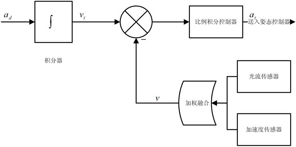
[0040] The technical scheme adopted in the present invention is: adopt the method for optical flow sensor and acceleration sensor data fusion to be used in the positioning system of unmanned aerial vehicle, comprise the following steps:

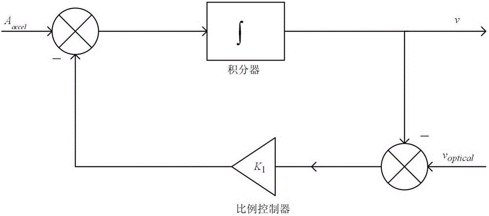
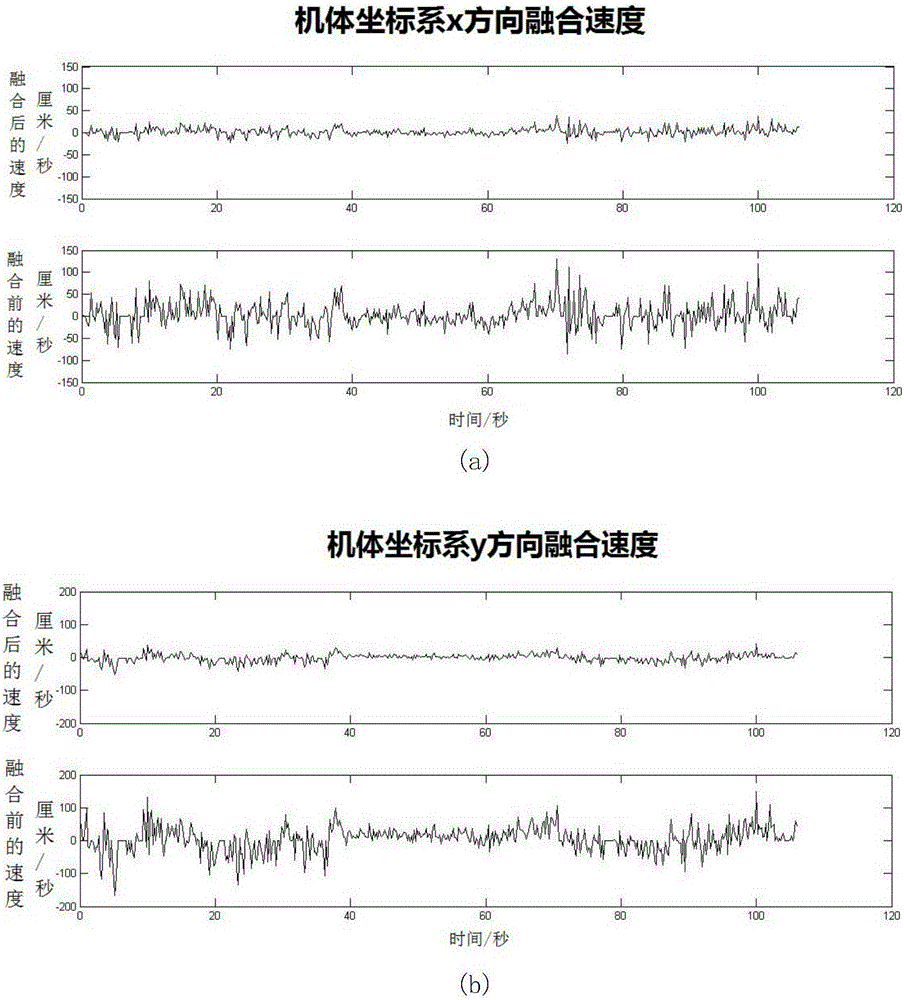
[0041] Use the optical flow sensor installed at the bottom of the quadrotor UAV to obtain the speed information and speed information processing of the UAV, use the acceleration sensor on the flight controller PCB board to obtain the acceleration position information of the UAV, and use a complementary filter to convert the above The data is fused to obtain a more accurate relative speed between the UAV and the ground.

[0042] The speed information and speed information proce...


PUM


Abstract

The invention relates to unmanned-plane positioning methods, and provides a novel self-adaptive secondary noise-spot detection method based on direction information. The method is capable of effectively reducing misjudgement probability of non-noise spot, is capable of relatively effectively removing salt and pepper noise in images, and is relatively strong in noise-removal robustness on different-intensity noise. Therefore, the employed technical scheme comprises that in the unmanned-plane horizontal-speed control method based on fusion of data of an acceleration sensor and an optical-flow sensor, the optical-flow sensor installed at the bottom of a quadrotor unmanned plane is utilized for acquiring the horizontal speed information of the unmanned plane, the acceleration sensor installed on the flight controller PCB is utilized for acquiring the acceleration information of the unmanned plane, the above data are fused by employing a complementary filter, and the speed of the unmanned plane relative to ground is relatively precisely obtained. The method is mainly applied to positioning of unmanned planes.

Description

technical field [0001] The invention relates to a positioning method for a drone, in particular to an autonomous positioning method for a drone based on data fusion of an acceleration sensor and an optical flow sensor. technical background [0002] The positioning problem of the UAV mainly refers to the use of its own sensors to determine the position and attitude information of the UAV relative to the inertial coordinate system in the flight environment. Accurate pose estimation is the premise and basis for complex flight tasks such as safe flight, trajectory planning, and target tracking of quadrotor UAVs. [0003] At present, the widely used UAV navigation system is mainly based on the GPS positioning method, but its positioning accuracy is low, and there is almost no signal indoors, so the GPS sensor cannot be used to realize the positioning flight of the UAV indoors. [0004] Chiba University in Japan uses the real-time optical flow vision system for the positioning an...

Claims


Application Information

Patent Timeline
IPC IPC(8): G01C21/00G01C21/20
CPCG01C21/005G01C21/206
Inventor 鲜斌金鑫
Owner TIANJIN UNIV
Features
  • R&D
  • Intellectual Property
  • Life Sciences
  • Materials
  • Tech Scout
  • Unparalleled Data Quality
  • Higher Quality Content
  • 60% Fewer Hallucinations
Learn More