
Extruding mechanism used for rubber

A technology of rubber and tapered holes, which is applied in the field of plastic molding or connection, and can solve problems such as low extrusion pressure and rubber that do not meet the requirements

Inactive Publication Date: 2016-03-02
CHONGQING BANAN DISTRICT XINXING RUBBER FACTORY
View PDF0 Cites 0 Cited by
  • Summary
  • Abstract
  • Description
  • Claims
  • Application Information

AI Technical Summary

Problems solved by technology

[0005] The rubber extrusion process is usually extruded in the extrusion mechanism. The existing extrusion mechanism usually includes an extrusion cylinder and an extrusion screw. The extrusion cylinder is provided with a cylindrical cavity, and the extrusion screw is located in the cylindrical cavity. However, during the extrusion process, especially when the operation of the rubber extrusion mechanism is frequently stopped and restarted, the amount of rubber just extruded from the extrusion cylinder is small, and the extrusion pressure is small, so it is usually extruded The rubber produced does not meet the requirements

Method used


Image

  • Extruding mechanism used for rubber
  • Extruding mechanism used for rubber

Examples


Embodiment 1

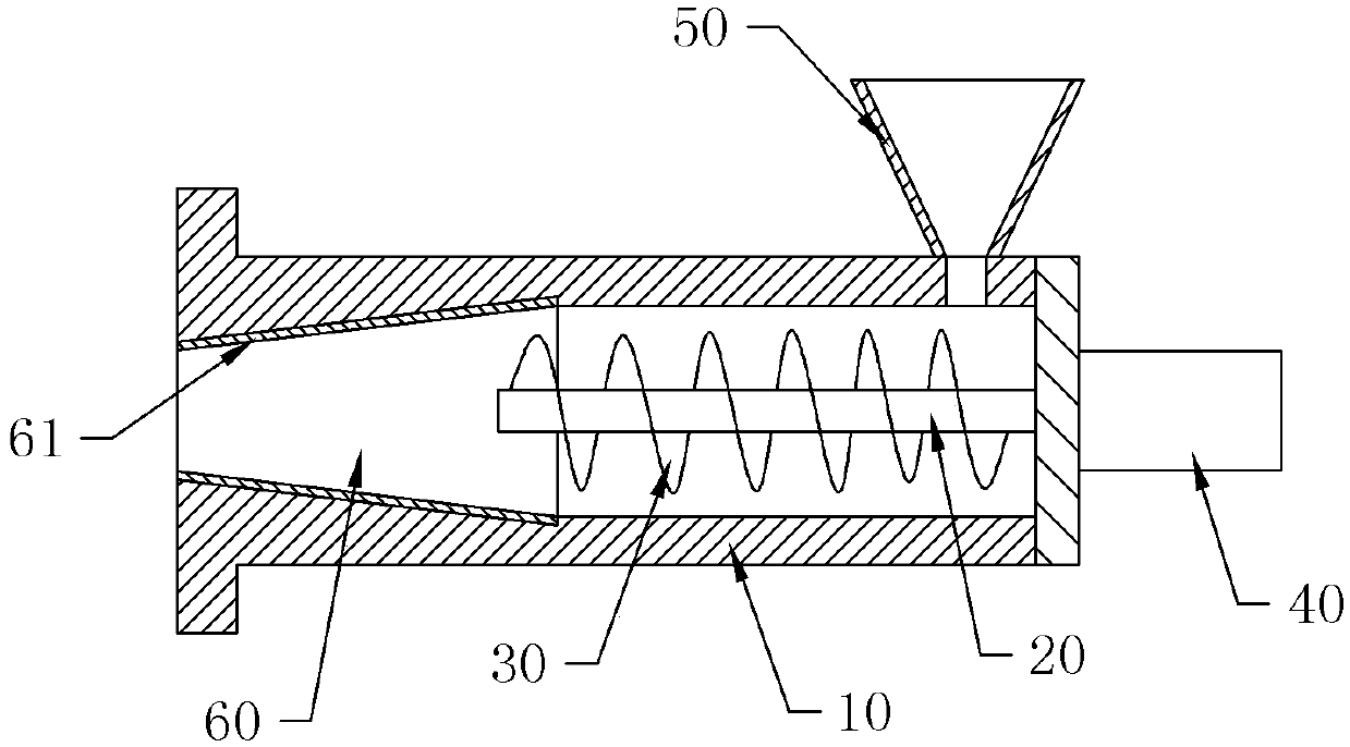
[0019] The embodiment is basically as attached figure 1 Shown: an extrusion mechanism for rubber, including an extrusion cylinder 10, a rotating shaft 20, a feeding screw 30 and a power source for driving the rotating shaft 20 to rotate. The power source used in this embodiment is a hydraulic motor 40, and the feeding screw 30 is connected to On the rotating shaft 20, an extrusion cavity is provided in the extrusion cylinder 10, and the rotation shaft 20 is located in the extrusion cavity. The extrusion cylinder 10 is provided with a feed hopper 50 communicating with the extrusion cavity. The tapered hole section 60 connected to the discharge side of the extrusion chamber has a taper of 1:5, and the diameter of the tapered hole section 60 gradually decreases along the extrusion direction.

[0020] In this embodiment, a heat-resistant alloy layer 61 is provided on the inner wall of the tapered hole section 60 . The tapered hole section 60 is subject to greater extrusion and fr...

Embodiment 2

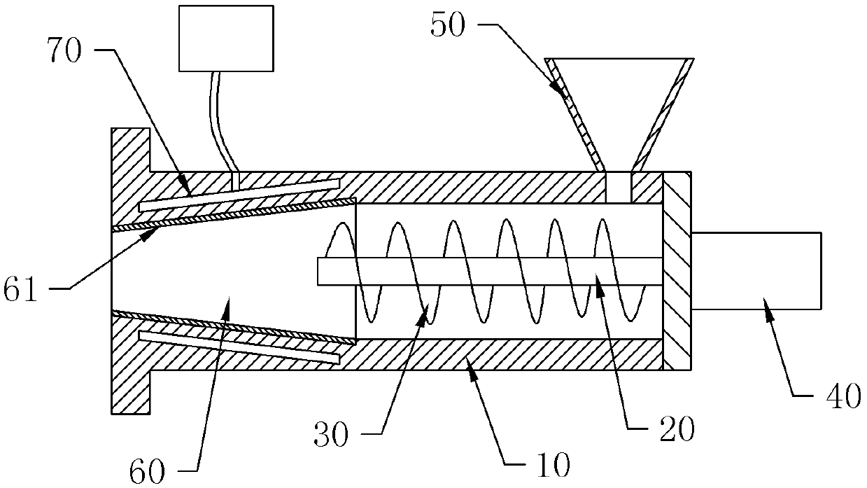
[0022] Such as figure 2 As shown, the difference from Embodiment 1 is that in this embodiment, an annular cooling cavity 70 is provided on the tapered hole section 60, and liquid inlets communicating with the cooling cavity 70 are provided on the tapered hole section 60 And the liquid outlet, the liquid inlet communicates with the external coolant through the coolant pipe. The rubber raw material is extruded in the tapered hole section 60, and the friction between the rubber raw material and the inner wall of the tapered hole section 60 will generate more heat. The cooling liquid is passed inside, so that it can absorb heat, so as to ensure that the extruded rubber products are qualified.

[0023] Specific working principle:

[0024] Take embodiment 1 as an example to describe in detail below: figure 1 As shown, during specific use, the hydraulic motor 40 is started, and the hydraulic motor 40 drives the feeding screw 30 to rotate, and then the rubber material to be extrud...


PUM


Abstract

The invention discloses an extruding mechanism used for rubber. The extruding mechanism used for the rubber comprises an extruding cylinder, a rotating shaft, a material feeding spiral and a power source driving the rotating shaft to rotate. The material feeding spiral is connected to the rotating shaft. An extruding cavity is formed in the extruding cylinder. The rotating shaft is located in the extruding cavity. A material feeding hopper communicated with the extruding cavity is arranged on the extruding cylinder. The extruding cylinder is further provided with a taper hole section communicated with the material discharging side of the extruding cavity. The taper size of a taper hole is 1:4-6, and the diameter of the taper hole section is decreased gradually in the extruding direction. According to the extruding mechanism used for the rubber, the extruding pressure of the newly-extruded rubber from the extruding cylinder can be sufficient under the conditions of the frequent shut-down operations and the restarting operations of the extruding mechanism, and thus the extruded rubber meets the requirements.

Description

technical field [0001] The invention belongs to the field of molding or connection of plastics, and in particular relates to an extruding mechanism for rubber. Background technique [0002] Early rubber was latex taken from plants such as rubber trees and rubber grasses, which were processed into materials with elasticity, insulation, impermeability to water and air. Highly elastic polymer compounds are divided into two types: natural rubber and synthetic rubber. Natural rubber is processed by extracting gum from rubber trees, rubber grass and other plants; synthetic rubber is obtained by polymerization of various monomers. [0003] The rubber industry is one of the important basic industries of the national economy. It not only provides daily and medical light industrial rubber products that are indispensable for people’s daily life, but also provides various rubber production equipment or rubber parts for mining, transportation, construction, machinery, electronics and o...

Claims


Application Information

Patent Timeline
IPC IPC(8): B29C47/38B29C47/66B29C47/80B29C48/395
CPCB29C48/397B29C48/6803B29C48/681B29C48/834
Inventor 熊鑫
Owner CHONGQING BANAN DISTRICT XINXING RUBBER FACTORY
Learn More