
Method of tracing voltage sag source by using sequence active increment current direction

A voltage sag source and voltage sag technology, which is applied in the direction of measuring electricity, measuring electrical variables, measuring devices, etc., can solve the problems of low voltage sag positioning accuracy and inability to apply to complex grid grids

Active Publication Date: 2016-03-09
CHINA UNIV OF MINING & TECH +2
View PDF12 Cites 7 Cited by
  • Summary
  • Abstract
  • Description
  • Claims
  • Application Information

AI Technical Summary

Problems solved by technology

These positioning methods have relatively high positioning accuracy for voltage sags caused by symmetrical faults, but low accuracy for voltage sags caused by asymmetrical faults, and are only suitable for single-circuit radial power grids
The third category is perturbation method [11-14] , although the perturbation method has solved the problem of locating the source of the voltage sag well, it needs to set up a phase-locked loop for synchronous sampling
It should be noted that this method, like the first and second methods, is only applicable to radial distribution networks, and cannot be applied to complex grid networks like the disturbance method

Method used


Image

  • Method of tracing voltage sag source by using sequence active increment current direction
  • Method of tracing voltage sag source by using sequence active increment current direction
  • Method of tracing voltage sag source by using sequence active increment current direction

Examples


Embodiment

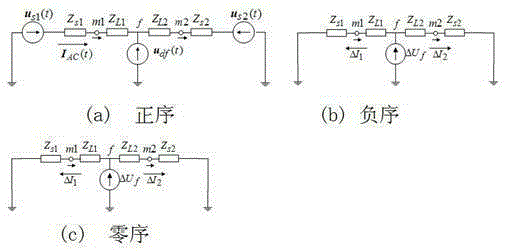
[0041] Example: Follow the steps below to trace the source of the voltage sag

[0042] Step a. When the power grid is operating normally, that is, before the voltage sag occurs, the three-phase voltage and current are sampled at each fundamental cycle at the monitoring point N points: , , and , , ; For the neutral point effectively grounded grid, calculate the root mean square value of each relative ground voltage by formula (1); for the neutral point non-effectively grounded grid, calculate the mean square value of each relative grid neutral point voltage by formula (2) root value; when the root mean square value of any phase voltage is less than 90% of the rated phase voltage, a voltage sag disturbance event occurs;

[0043] (1)

[0044] (2)

[0045] here, , , monitoring points mi Measured three-phase voltage , , root mean square value of is the zero-sequence voltage of the power grid; the three-phase-to-ground voltage of the neutral point ef...


PUM


Abstract

The invention discloses a method of tracing a voltage sag source by using a sequence active increment current direction. A positive value or a negative value of a positive-sequence and a negative-sequence active increment current value before grid fault and during the fault is used for judging the position of the voltage sag source. A corresponding positive-sequence and negative-sequence active increment current algorithm is given, and the provided voltage sag source recognition method can correctly judge the voltage sag source positions caused by various kinds of grid fault, is applicable to a radial distribution network and positioning of other disturbance sources.

Description

technical field [0001] The invention relates to an automatic monitoring and positioning method for a pollution source that affects the power quality of power grid power supply, in particular to an automatic monitoring and positioning method for locating a grid voltage sag source. Background technique [0002] Voltage sag refers to a phenomenon in which the root mean square value of the supply voltage suddenly drops to 90%~10% of the rated voltage amplitude in a short period of time, and its typical duration is 10ms~1min. Some highly automated equipment is easily affected by voltage sags, and several cycles of voltage sags will cause huge economic losses to industrial production. According to foreign surveys, voltage sags have become the main cause of complaints in power quality problems, and even account for 80% of complaints. However, electric energy is a special product that is provided by the power sector to power users and whose quality is jointly guaranteed by both the...

Claims


Application Information

Patent Timeline
IPC IPC(8): G01R31/08
CPCG01R31/086G01R31/088
Inventor 唐轶时昀陈奎刘昊倪冰
Owner CHINA UNIV OF MINING & TECH
Learn More