Machining device control system with movable machining head

A processing device and control system technology, applied in metal processing equipment, manufacturing tools, welding equipment, etc., can solve the problems of complex structure of processing head, increase in quality, increase in cost, difficulty in control, etc.

Inactive Publication Date: 2016-03-16
HANGZHOU FUNA GLASSES CO LTD
View PDF7 Cites 0 Cited by
  • Summary
  • Abstract
  • Description
  • Claims
  • Application Information

AI Technical Summary

Problems solved by technology

However, this kind of motion superposition method often adopts to set the driving element again on a driving block, which is easy to cause t

Method used


Image

  • Machining device control system with movable machining head
  • Machining device control system with movable machining head
  • Machining device control system with movable machining head

Examples


Embodiment Construction

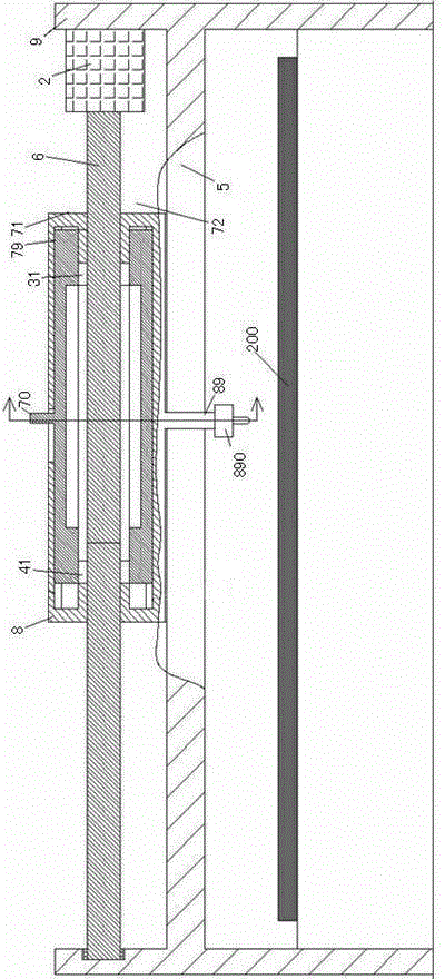
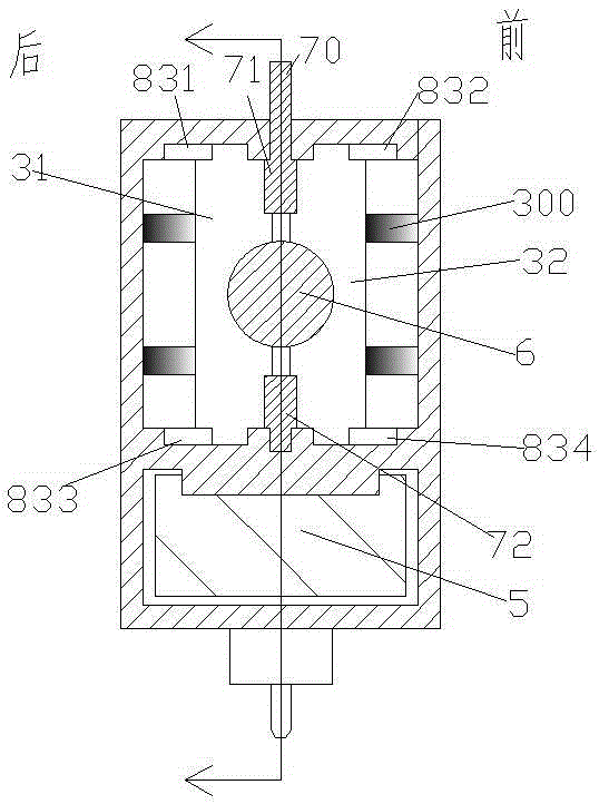
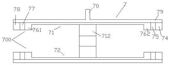
[0012] Combine below Figure 1-5 The present invention will be described in detail.

[0013] According to an embodiment, a processing device control system with a movable processing head is used for machining a workpiece 200, including a DSP controller, a motor drive circuit, a frame 9, a moving frame 8 and a lower side fixed on the moving frame 8 The connection part 89 for connecting with the processing head 890, wherein the left and right extending screw rod 6 driven by the motor 2 and rotatably installed on the frame 9 extends through the moving frame 8, and the moving frame 8 It is slidably carried on the rail beam 5 extending left and right fixedly connected with the frame 9, and the moving frame 8 is provided with a left threaded block group and a right threaded block group respectively, and the left threaded block group includes a left threaded block group The front threaded block 32 and the rear threaded block 31 of the left group, and under the action of the pressing...


PUM


Abstract

A machining device control system with a movable machining head is used for machining a workpiece (200) and comprises a DSP controller, a motor drive circuit, a rack (9), a moving frame (8) and a connecting part (89) fixed at the lower side of the moving frame (8) and used for being connected with the machining head (890), wherein a left-right extending screw rod (6) driven by a motor (2) and rotatably arranged on the rack (9) extends to penetrate through the moving frame (8), the moving frame (8) is slidably carried on a left-right extending rail crossbeam (5) fixedly connected with the rack (9), a left threaded block group and a right threaded block group are arranged in the moving frame (8) respectively, and the left threaded block group comprises a left group front threaded block (32) and a left group rear threaded block (31).

Description

technical field [0001] The invention relates to the processing field, in particular to a processing device control system with a movable processing head. Background technique [0002] In the field of processing machinery, such as in the field of laser cutting processing, due to the increase in automation requirements, it is often necessary to automatically control the walking and speed of the processing head. In the existing technology, the way of screw drive is often used to drive to realize the walking motion of the processing head. Such a driving method has advantages, such as precise transmission and position locking function after power off. [0003] However, there are also disadvantages in these powered approaches. For example, the processing head sometimes needs to move quickly with low precision, such as in the case of rough machining or in the case of pure idling of the processing head; sometimes it needs to move with high precision and slow speed, such as in the ...

Claims


Application Information

Patent Timeline
IPC IPC(8): B23K26/38
CPCB23K26/38
Inventor 丁凯项
Owner HANGZHOU FUNA GLASSES CO LTD
Why Eureka
Try Eureka