Machining device allowing machining head to be moved and prolonging service life

A processing device and processing head technology, applied in metal processing equipment, metal processing mechanical parts, manufacturing tools, etc., can solve the problems of complex structure of processing head, increase in quality, increase in cost, difficulty in control, etc.

Inactive Publication Date: 2016-03-23
吴岳微
View PDF2 Cites 0 Cited by
  • Summary
  • Abstract
  • Description
  • Claims
  • Application Information

AI Technical Summary

Problems solved by technology

However, this kind of motion superposition method often adopts to set the driving element again on a driving block, which is easy to cause t

Method used


Image

  • Machining device allowing machining head to be moved and prolonging service life
  • Machining device allowing machining head to be moved and prolonging service life
  • Machining device allowing machining head to be moved and prolonging service life

Examples


Embodiment Construction

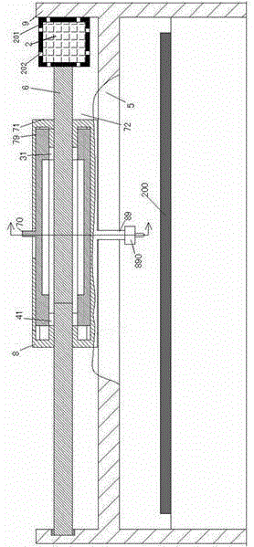
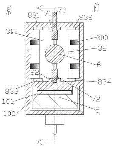
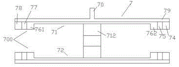
[0011] Combine below Figure 1-4 The present invention will be described in detail.

[0012] According to an embodiment, a processing device with a movable processing head and improved service life is used for machining a workpiece 200. The connection part 89 of connection, wherein, the screw rod 6 that is driven by the motor 2 and is rotatably installed on the frame 9 extending left and right extends through the moving frame 8, and the moving frame 8 is slidably carried on the On the track beam 5 extending left and right that the frame 9 is fixedly connected to, a groove 101 is provided at the connection between the track beam 5 and the mobile frame 8, and a roller 102 is arranged in the groove 101, and the roller The shaft 102 is rollingly connected with the moving frame 8, and the roller 102 is used to reduce the frictional force generated when sliding between the moving frame 8 and the track beam 5, so as to improve flexibility. In the moving frame 8, respectively A left...


PUM


Abstract

The invention provides a machining device allowing a machining head to be moved and prolonging the service life. The machining device is used for machining a work-piece (200) and comprises a rack (9), a movable rack (8) and a connecting portion (89), wherein the connecting portion (89) is fixed to the lower side of the movable rack (8) and used for being connected with the machining head (890). A threaded rod (6) is driven by a motor (2) and rotatablely installed on the rack (9), extends left and right and extends to penetrate through the movable rack (8). The movable rack (8) is borne on a track beam (5) in a sliding mode, wherein the track beam (5) is fixedly connected with the rack (9) and extends left and right. A groove (101) is formed in the connecting portion of the track beam (5) and the movable rack (8). A rolling shaft (102) is arranged in the groove (101) and connected with the movable rack (8) in a rolling mode. A left thread block set and a right thread block set are arranged in the movable rack (8). The left thread block set comprises a left-set front thread block (32) and a left-set rear thread block (31).

Description

technical field [0001] The invention relates to the processing field, in particular to a processing device with a movable processing head and improved service life. Background technique [0002] In the field of processing machinery, such as in the field of laser cutting processing, due to the increase in automation requirements, it is often necessary to automatically control the walking and speed of the processing head. In the existing technology, the way of screw drive is often used to drive to realize the walking motion of the processing head. Such a driving method has advantages, such as precise transmission and position locking function after power off. [0003] However, there are also disadvantages in these powered approaches. For example, the processing head sometimes needs to move quickly with low precision, such as in the case of rough machining or in the case of pure idling of the processing head; sometimes it needs to move with high precision and slow speed, such...

Claims


Application Information

Patent Timeline
IPC IPC(8): B23Q1/46B23K26/08
CPCB23K26/0869B23Q1/46
Inventor 吴岳微
Owner 吴岳微
Why Eureka
Try Eureka