Unlock instant, AI-driven research and patent intelligence for your innovation.
Motor-driven hydraulic clutch and automobile
What is Al technical title?
Al technical title is built by PatSnap Al team. It summarizes the technical point description of the patent document.
A hydraulic clutch and motor-driven technology, which is applied in the direction of non-mechanical drive clutches, clutches, mechanical equipment, etc., can solve problems affecting driving safety, operator fatigue, etc., and achieve the effects of compact structure, high reliability, and convenient installation
Active Publication Date: 2016-03-16
武汉理工通宇新源动力有限公司
View PDF6 Cites 3 Cited by
Summary
Abstract
Description
Claims
Application Information
AI Technical Summary
This helps you quickly interpret patents by identifying the three key elements:
Problems solved by technology
Method used
Benefits of technology
Problems solved by technology
[0004] The above-mentioned hydraulic clutch realizes the power transmission of the car by stepping on the clutch pedal by the operator. It needs the tight cooperation between the accelerator and the clutch to complete each gear shift smoothly, which will easily make the operator tired and affect driving safety.
Method used
Image
Click on the blue label to locate the original text in one second.
Reading with bidirectional positioning of images and text.
Examples
Embodiment 1
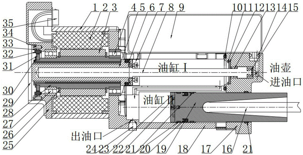
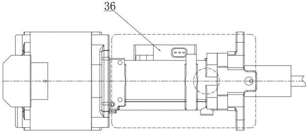
[0054] The invention provides a motor-driven hydraulic clutch, the structural diagram of which is as follows figure 1 and figure 2 shown, including:
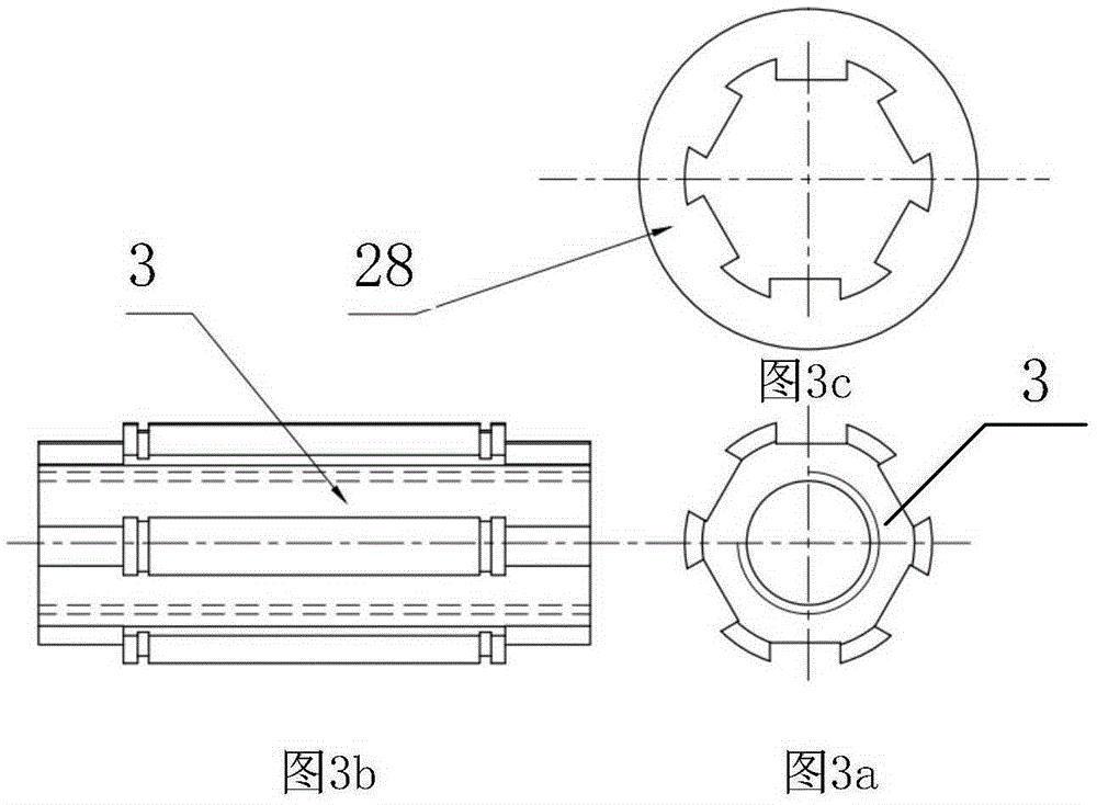
[0055] Motor housing 1, motor stator coil 2, motor rotor 3, first deep groove ball bearing 4, trapezoidal screw rod 5, first hydraulic sealing ring 6, anti-rotation block 7, anti-rotation square rod 8, oil pot 9, The first O-ring 10, the first circlip 11, the retainer 12, the spring 13, the second O-ring 14, the cup 15, the clutch push rod 16, the cylinder end cover 17, the cylinder 18, the piston 19, the first Two hydraulic sealing rings 20, wear-resistant rings 21, displacement sensor magnetic rings 22, magnetic ring holders 23, plugs 24, motor rear end covers 25, second circlips 26, second deep groove ball bearings 27, trapezoidal screw rods Nut 28, rear end cover 29, fixed plate 30, resolver rotor 31, resolver stator 32, stator pressing piece 33, screw 34, connector 35 and displacement sensor 36.
[0056] The connection ...
Embodiment 2
[0081] The invention provides an automobile with a motor-driven hydraulic clutch. The automobile includes the above-mentioned motor-driven hydraulic clutch. The motor-driven hydraulic clutch is arranged between the engine and the gearbox to cut off or transmit the power transmitted from the engine to the gearbox.
PUM
Abstract
The invention relates to a motor-driven hydraulic clutch and an automobile, wherein a motor stator coil (2) is powered on to control a motor rotor (3) to rotate; a hollow part of the motor rotor (3) and a trapezoidal screw nut (28) are fixed together; the hollow part rotates to drive the trapezoidal screw nut (28) which is inside the hollow part; a trapezoidal screw rod (5) is matched with the trapezoidal screw nut (28), does rectilinear motion with rotation of the trapezoidal screw nut (28) and is used for pushing hydraulic oil in an oil cylinder I into an oil cylinder II and pushing a piston (19) to move; the piston (19) inside the oil cylinder II moves to drive a clutch push rod (16) to move; a displacement sensor magnetic ring (22) is mounted on the piston (19); a displacement sensor (36) is matched with the displacement sensor magnetic ring (22) to detect the displacement of the clutch push rod (16). The motor-driven hydraulic clutch disclosed by the invention is capable of realizing automatic clutching, and no extra hydraulic source is needed, so that the overall executing mechanism is compact in structure, convenient to install and relatively high in reliability.
Description
technical field [0001] The invention belongs to the field of automobiles, and in particular relates to a motor-driven hydraulic clutch and an automobile. Background technique [0002] Hydraulic clutches are widely used in the automotive field because of their large torque transmission capacity, small size, no impact, and smooth starting and reversing. [0003] The automobile clutch is installed in the flywheel housing between the engine and the gearbox, and is fixed on the rear plane of the flywheel; the output shaft of the clutch is connected with the input shaft of the gearbox. This hydraulic clutch is mainly composed of a clutch push rod, a main pump, a slave pump and a clutch pedal. During the running of the car, the operator can step on or release the clutch pedal as needed, and use the hydraulic oil in the main pump and the slave pump as the transmission medium to transmit the force of stepping on the clutch pedal to the clutch push rod. The function is to temporaril...
Claims
Application Information
Patent Timeline
Application Date:The date an application was filed.
Publication Date:The date a patent or application was officially published.
First Publication Date:The earliest publication date of a patent with the same application number.
Issue Date:Publication date of the patent grant document.
PCT Entry Date:The Entry date of PCT National Phase.
Estimated Expiry Date:The statutory expiry date of a patent right according to the Patent Law, and it is the longest term of protection that the patent right can achieve without the termination of the patent right due to other reasons(Term extension factor has been taken into account ).
Invalid Date:Actual expiry date is based on effective date or publication date of legal transaction data of invalid patent.

